Background
advertisement
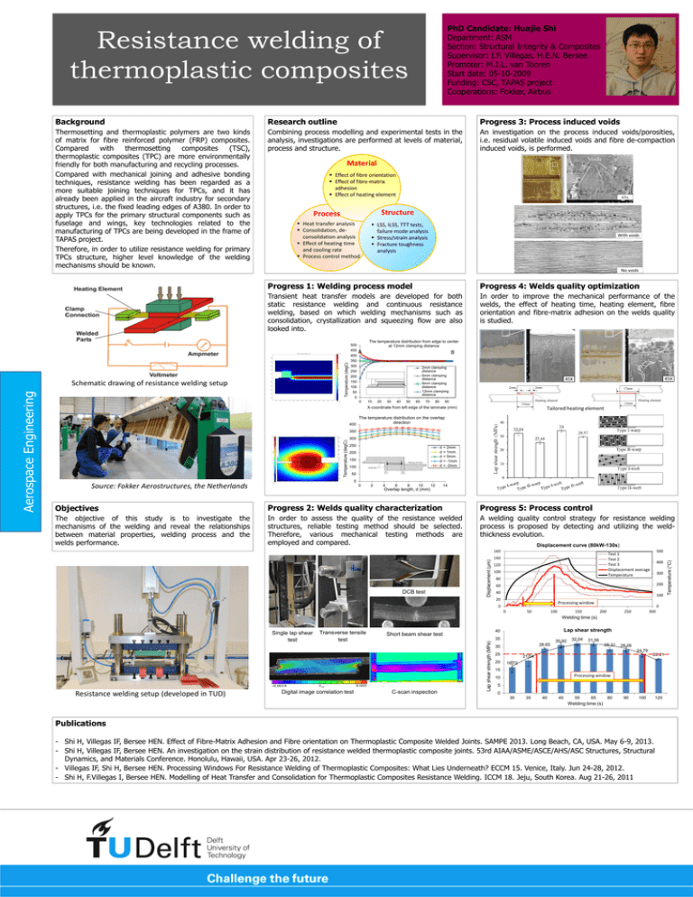
PhD Candidate: Huajie Shi Department: ASM Section: Structural Integrity & Composites Supervisor: I.F. Villegas, H.E.N. Bersee Promoter: M.J.L. van Tooren Start date: 05-10-2009 Funding: CSC, TAPAS project Cooperations: Fokker, Airbus Resistance welding of thermoplastic composites Background Research outline Progress 3: Process induced voids Thermosetting and thermoplastic polymers are two kinds of matrix for fibre reinforced polymer (FRP) composites. Compared with thermosetting composites (TSC), thermoplastic composites (TPC) are more environmentally friendly for both manufacturing and recycling processes. Compared with mechanical joining and adhesive bonding techniques, resistance welding has been regarded as a more suitable joining techniques for TPCs, and it has already been applied in the aircraft industry for secondary structures, i.e. the fixed leading edges of A380. In order to apply TPCs for the primary structural components such as fuselage and wings, key technologies related to the manufacturing of TPCs are being developed in the frame of TAPAS project. Therefore, in order to utilize resistance welding for primary TPCs structure, higher level knowledge of the welding mechanisms should be known. Combining process modelling and experimental tests in the analysis, investigations are performed at levels of material, process and structure. An investigation on the process induced voids/porosities, i.e. residual volatile induced voids and fibre de-compaction induced voids, is performed. Material Effect of fibre orientation Effect of fibre-matrix adhesion Effect of heating element 65x Structure Process Heat transfer analysis Consolidation, deconsolidation analysis Effect of heating time and cooling rate Process control method LSS, ILSS, TTT tests, failure mode analysis Stress/strain analysis Fracture toughness analysis With voids No voids Progress 1: Welding process model Progress 4: Welds quality optimization Transient heat transfer models are developed for both static resistance welding and continuous resistance welding, based on which welding mechanisms such as consolidation, crystallization and squeezing flow are also looked into. In order to improve the mechanical performance of the welds, the effect of heating time, heating element, fibre orientation and fibre-matrix adhesion on the welds quality is studied. The temperature distribution from edge to center at 12mm clamping distance 500 450 Temperature (degC) 400 Schematic drawing of resistance welding setup A B 350 300 2mm clamping distance 6mm clamping distance 9mm clamping distance 12mm clamping distance 250 200 150 100 50 0 0 10 20 30 40 50 60 70 80 45X 45X 2mm 2mm 17mm Heating element Heating element 90 13mm 13mm X-coordinate from left edge of the laminate (mm) Tailored heating element The temperature distribution on the overlap direction 400 350 Temperature (degC) 300 250 d = 2mm d = 1mm d = 0mm d = -1mm d = -2mm 200 150 100 50 0 Source: Fokker Aerostructures, the Netherlands 0 2 4 6 8 10 12 14 Overlap length, d (mm) Objectives Progress 2: Welds quality characterization Progress 5: Process control The objective of this study is to investigate the mechanisms of the welding and reveal the relationships between material properties, welding process and the welds performance. In order to assess the quality of the resistance welded structures, reliable testing method should be selected. Therefore, various mechanical testing methods are employed and compared. A welding quality control strategy for resistance welding process is proposed by detecting and utilizing the weldthickness evolution. Displacement curve (80kW-130s) 500 Test 1 Test 2 Test 3 Displacement average Temperature 140 120 100 80 400 300 200 60 40 100 20 Processing window 0 0 50 100 150 0 200 250 300 Welding time (s) Single lap shear test -0.0018 Resistance welding setup (developed in TUD) Transverse tensile test exy Digital image correlation test Lap shear strength 40 Short beam shear test 35 0.005 C-scan inspection 28.65 30 32.04 31.56 28.32 28.06 24.79 25 20 30.92 22.21 21.04 16.72 15 Processing window 10 5 0 30 35 40 45 55 65 80 90 100 Welding time (s) Publications - Shi H, Villegas IF, Bersee HEN. Effect of Fibre-Matrix Adhesion and Fibre orientation on Thermoplastic Composite Welded Joints. SAMPE 2013. Long Beach, CA, USA. May 6-9, 2013. - Shi H, Villegas IF, Bersee HEN. An investigation on the strain distribution of resistance welded thermoplastic composite joints. 53rd AIAA/ASME/ASCE/AHS/ASC Structures, Structural Dynamics, and Materials Conference. Honolulu, Hawaii, USA. Apr 23-26, 2012. - Villegas IF, Shi H, Bersee HEN. Processing Windows For Resistance Welding of Thermoplastic Composites: What Lies Underneath? ECCM 15. Venice, Italy. Jun 24-28, 2012. - Shi H, F.Villegas I, Bersee HEN. Modelling of Heat Transfer and Consolidation for Thermoplastic Composites Resistance Welding. ICCM 18. Jeju, South Korea. Aug 21-26, 2011 120 Temperature ( C) DCB test Displacement (μm) 160 Lap shear strength (MPa) Aerospace Engineering Voids

