result & discussion
advertisement
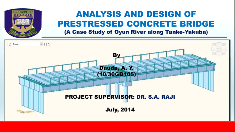
ANALYSIS AND DESIGN OF PRESTRESSED CONCRETE BRIDGE (A Case Study of Oyun River along Tanke-Yakuba) By Dauda, A. Y. (10/30GB105) PROJECT SUPERVISOR: DR. S.A. RAJI July, 2014 The aim of this project is to analyze and design a prestressed concrete bridge to link Tanke F division area with Apata Yakuba in Ilorin. The specific objectives used in achieving this are; Obtaining measurement for the width and depth of the river Determining the reactions at the bridge support, stresses on girders and walls, and deformation on the bridge using Midas CIVIL engineering software SCOPE AND LIMITATION This project focuses on analysing and designing a prestressed concrete bridge. The project is limited to the modeling, detailed analyses and design of the bridge with Computer Aided Design software (MIDASCivil) and comparing results with that obtained from the manual analysis of a major girder of the bridge.. INTRODUCTION A bridge is a structure erected to span natural or artificial obstacles, such as rivers, highways, or railroads, and supporting a footpath or roadway for pedestrian, highway, or rail road traffic. A number of different methods may be used to classify bridges. Bridges can be classified according to materials (concrete, steel, or wood), usage (pedestrian, highway, or railroad), span (short, medium, or long), or structural form (slab, girder, truss, arch, suspension, or cable-stayed). METHODOLOGY Modeling of the bridge Computer aided analysis of the bridge Computation of reactions, stresses and deformations on the bridge using Midas CIVIL engineering software Manual Analysis of the bridge to serve as a check COMPUTER MODELLING PROCEDURE USING MIDAS CIVIL RESULT & DISCUSSION From manual and MIDAS calculations The stresses in girder (No 895) are LEVEL MANUAL MIDAS 1 BOTTOM 20.89𝑁/𝑚𝑚2 30.3𝑁/𝑚𝑚2 2 TOP −1.2𝑁/𝑚𝑚2 −1.72𝑁/𝑚𝑚2 CONCLUSION 1. Based on the results from both manual and computer application, it can be concluded that the bridge girder (No 895) has a stress of 20.89𝑁/𝑚𝑚2 (𝑡𝑒𝑛𝑠𝑖𝑙𝑒 𝑠𝑡𝑟𝑒𝑠𝑠) at the bottom of the beam and −1.2𝑁/𝑚𝑚2 𝑐𝑜𝑚𝑝𝑟𝑒𝑠𝑠𝑖𝑣𝑒 𝑠𝑡𝑟𝑒𝑠𝑠 at the top of the beam from the manual calculation while the computer aided analysis gave 30.3𝑁/𝑚𝑚2 (𝑡𝑒𝑛𝑠𝑖𝑙𝑒 𝑠𝑡𝑟𝑒𝑠𝑠) at the bottom and −1.72𝑁/ 𝑚𝑚2 𝑐𝑜𝑚𝑝𝑟𝑒𝑠𝑠𝑖𝑣𝑒 𝑠𝑡𝑟𝑒𝑠𝑠 at the top. 2. The use of the finite element method of analysis was justified and the application of the MIDAS/ Civil software was found to be time saving, less tiring and of higher accuracy compared with rigorous manual method of analysis. RECOMMENDATION 1. It is recommended that the use of this software be treated in broad term for all engineers due to its wide applications. 2. More research should be carried out in the future on better ways of structural modeling and analysis of bridge. REFERENCE Barker R. M and Puckett (2007). Design of highway bridges. John Wiley & Sons, Inc. Canada Chen W.F. and Duan L. (2000). Bridge Engineering Handbook. CRC Press, Boca Raton, FL Gurfinkel G. and Khachaturian N (1965). Ultimate design of prestressed concrete beams. University of Illinois Bulletin, Volumn 62, Number 79 Jackson P. (2008). Design of reinforced concrete bridges. ICE Manual of Bridge Engineering Knippers, J and Gabler, M (2006). New Design Concepts for Advanced Composite Bridges – The Friedberg Bridge in Germany. IABSE Symposium pp. 16-23(8). International Association for Bridge and Structural Engineering Lai S.G. (1998). Guidelines for design of small bridges and culverts. Journal of the Indian Roads Congress Mekdam N, Nolan D, and Tony R (2010).Design and Construction of the Saint Albert Bridge. Annual Conference of the Transportation Association of Canada. Nova Scotia


