presentation
advertisement
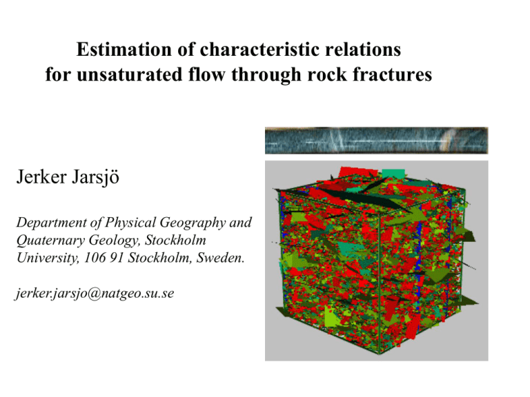
Estimation of characteristic relations for unsaturated flow through rock fractures Jerker Jarsjö Department of Physical Geography and Quaternary Geology, Stockholm University, 106 91 Stockholm, Sweden. jerker.jarsjo@natgeo.su.se Areas of fundamental research (1) Characteristics of multiphase flow in fractured rock under different ambient conditions (2) Dependence on quantifiable fracture characteristics (aperture distribution, connectivities) (3) Multiphase flow in soil and fractured rock: Similarities and differences. -Are parameter translations of characteristic curves possible? Relevance? Useful for prediction of… • Conductivity of gas or non-aqueous phase liquids (NAPLS) in fractured media • Immobilization and trapping of NAPLS in fractured media Application examples: • Storage of waste /oil in bedrock • Storage of carbon dioxide storage in deep saline aquifers and potential return flows • Movement of accidental oil spills in fractured media (Granite, karst, glaciers) Experimental determination of pressure – saturation (- conductivity) – relations in soil Step A-E: A B C Water saturation, S* * S = Vw/Vtot (Vw=vol. water, Vtot=total vol.) D E succesively increased underpressure (-) =0: atmospheric pressure Experimental determination of pressure – saturation (- conductivity) – relations in soil Step A-E: A B C D Water saturation, S* S =n A 0 succesively increased underpressure (-) =0: atmospheric pressure E B C D E The water saturation is a function of the underpressure, i.e. S= S(). Straightforward to determine experimentally underpressure (-, m.water column) Empirical vG relation 1 d h n 1 1 d h n 11 / n K ( h) = K s n m 11 / n 1 d h K(h)=Ks 2 for h<0 for h0 h = pc / g , pc=capillary pressure where d, n, m = fitting parameters Empirical vG relation Related to bubble pressure 1 d h n 1 1 d h n 11 / n K ( h) = K s n m 11 / n 1 d h K(h)=Ks 2 for h<0 Related to width of soil psd m=0.5 usually assumed for h0 h = pc / g , pc=capillary pressure where d, n, m = fitting parameters The cubic law for water flow in a fracture • Single fractures: relation between aperture (a) and fracture transmissivity T: g 3 T= a 12 ”Cubic law” ( =density, och µ =viscosity, and g=graviational constant) Direction of flow Direction of a a flow Cubic law: exact relation Cubic law: approximately true Fracture aperture relation 1h 5h Darker areas=wider aperture; gas=white 48 h (SKB TR-98-17 & 01-13 ) The fracture aperture distribution (and the mean aperture) can be measured in situ or in the lab Distribution of water and air in a fracture probability density function fln(a) cut-off aperture (ac) assumption water ac =2w/ pc gas air (gas) a cu aperture, a Water occupies the tighter parts, and air the wider parts. Similar to the porous medium case Fracture aperture relation For unsaturated fracture flow Predict relative fracture transmissivity through consideration of the cubic law (TR-98-17) Tus (w) ac Trel ( pc ; ln a , ln a ) = 3 a f ln (a; ln a , ln a )da 0 a 3 f ln (a; ln a , ln a )da 0 Ts us=unsaturated s=saturated w=water Fitting procedure Fitted v an Genuchten parameter: n_fit = 2.242 d_fit = 1.966 Trel and Krel [-] 1 Fracture based relation (eq. 5) 0.8 0.6 0.4 van Genuchtenrelation (eq. 6) 0.2 Trel=0.05 0 2 4 Capillary pressure, pc [kPa] 6 Considered T-data T-values estimated from hydraulic testing (R-07-48) 5-1 RFMxxx RFM029 RFM029 RFM029 RFM029 RFM029 RFM029 RFM029 RFM029 RFM029 RFM029 ZFMxxxx orSec-up FFMxx Sec-low FFM02 102 203 FFM01 203 216 Possible(G) 216 224 FFM01 224 267 ZFMENE1192 267 285 FFM01 285 386 ZFMENE1192 386 412 FFM01 412 639 ZFMENE2254 639 684 FFM01 684 1,001 Elev-up –98 –199 –212 –220 –262 –280 –380 –406 –630 –674 Elev-low –199 –212 –220 –262 –280 –380 –406 –630 –674 –982 No.PFL-f ST:PFL-F 23 1.92E-07 0 0 0 0 2 7.09E-10 2 7.79E-10 7 4.76E-09 0 0 0 0 0 0 0 0 Estimation of corresponding hydraulic aperture and mean aperture Hydraulic aperture*, ah Mean aperture**, a *assuming one single fracture **assuming a/ah=1.7 (cubic law) 6.1719E-05 0.10492228 0 0 0 0 9.53968E-06 0.016217456 9.84383E-06 0.016734515 1.79965E-05 0.030594002 0 0 0 0 0 0 0 0 (b) (b) Conclusions • Simple patterns emerge from the matching of seemingly complex curves • Fracture roughness related to the n-value of the van Genuchten-formulation: the rougher the fracture, the lower the matching n-value • Implies that characteristic curves derived from measurable aperture statistics can be described with soil-based van Genuchten parameters (standard description in most computer codes) Geological storage in deep saline aquifers Cap rock: confining unit – low permeability Storage formation: high permeability high porosity Feasable if return flows are sufficiently small (min 95% retained after 100 years) Storage potential in Sweden and investigation site Target: sandstone aquifer at 1670 m depth Representation in the TOUGH2 code Stratigraphic uncertainty Parameter value uncertainty …confidence interval for k Uncertainties addressed through scenario analyses Considered scenarios: A) Base case B) No upper barrier (thin claystone layer not continuous) C) High permeability (95% confidence limit) D) Combination B+C + simulations for different injection pressures Resulting plume migration (1000 days) Volumetric gas saturation [-] Salt precipitation – injectivity effects Permeability reduction factor k/k0 [-] Summary of plume behaviour Summary of plume behaviour Conclusions Stratigraphic uncertainty leads to large differences in predicted CO2 storage in target formation Parameter uncertainty (permeability) has small impact on CO2 storage predictions but affects injectivity Salt precipitation at the border of the target formation affects CO2 injectivity At low injection rates, salt precipitates within the target formation, decreasing its storage ability Journal reference: Chasset, C., Jarsjö, J., Erlström, M., Cvetkovic, V. and Destouni, G., 2011. Scenario simulations of CO2 injection feasibility, plume migration and storage in a saline aquifer, Scania, Sweden. International Journal of Greenhouse Gas Control, 5(5), 1303-1318. March 15, 2012 Airplane crash and kerosene spill on top of Kebnekaise mountain (Rabots glacier) Sweden / 2096.3 m 2101.3 m PROCESSES DETERMINING THE FATE OF THE HYDROCARBON POLLUTION Sampling of water 1/week + passive 13-14 July 160 mm precipitation (TRS) 15, 18 July traced og naftalen & PAH in Rabot jokk

