Installation & Operation
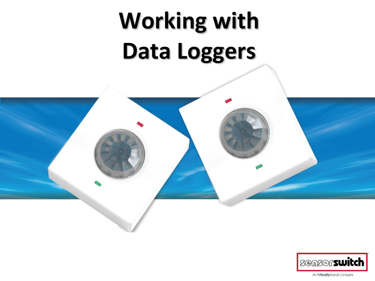
Working with
Data Loggers
Data Logger Loaner Program
• In order to loan loggers from Sensor Switch, please visit www.sensorswitch.com/datalogger/ then fill out and submit the provided form.
• Depending on the demand at any given time, it may take anywhere from 1-4 weeks to receive your order
(wait time increases with orders of multiple cases).
• A notification will be sent once cases are ready to be shipped. A tracking number is available upon request.
Opening Your Case
• Each case contains the following:
- 45x loggers
- 1x Standard B USB cable
- 1x USB Flash Drive
• The flash drive will contain:
- Software Suite Installer
- Data Logger Monitoring Form
- Data Logger Installation Guide
- Comprehensive Software Suite Quick Start Guide
Installing The Software Suite
• Ensure the computer you wish to install the software on is running Windows, version XP or higher (currently no Mac OS support) and insert the flash drive into a USB port.
• Double-click installer and let it run… this will only take a matter of seconds to complete.
Registering Your Account
• In order to utilize our software suite, you’ll need a Sensor Switch
Data Logger account. Click the “Register” button from the main
Data Logger Software Suite page.
• This brings you to a website.
Fill the basic form out completely. Once registered, you can log in and utilize the software suite, which will come into play after your loggers collect data.
The Data Logger Device
• Electronically calibrates to electronic and magnetic fluorescent or incandescent lights
• Records lights-on events
• Records occupancy
• Small Motion 360º lens
• Provides ~12ft radial coverage when mounted to a standard 9 ft ceiling
• 8-15ft mounting heights provide 10-20 ft of radial coverage
Data Logger Installation
1. Use a pin, or paperclip, to depress the recessed button on your logger for ~10 seconds, until the green LED flashes rapidly… this turns the logger ON.
2. Immediately after the LED flashes, press the same button three times in a row… this begins internal diagnostics \ calibration of the device, indicated by the alternating flashes of the orange and green LED lights. When calibrating, the Logger is “locking” on to a light source to track. This may take anywhere between 30-180 seconds.
Data Logger Installation
3. With your logger calibrating, peel the backing from the adhesive strip and stick the device to the ceiling in your desired location.
Data Logger Installation
4. Be sure to write down each logger’s serial number AND location on the Data
Logger Monitoring Form included on your USB flash drive. This ensures you have the necessary data to compile a report when you take the loggers down.
Data Logger Removal
Once data collection is complete (Sensor Switch recommends at least 2 weeks of monitoring to collect a good data sample), you may remove the loggers from their locations by pulling the tape tab to dislodge it from the ceiling.
Data Logger Removal
To prevent the collecting of data after you’ve removed the Loggers from the ceiling, you need to turn them off as you are collecting them.
To turn the Logger off, depress the programming button for approximately ten seconds, until the orange LED light flashes rapidly then turns off.
Managing Your Data
• The data captured on your Loggers must now be pulled and compiled prior to generating your reports.
• Requires use of the class B USB cable included in your case.
• Requires use of a filled-in Logger monitoring form.
Managing Your Data
• Open the Data Logger software suite via the icon on your desktop
• Click “User Job/Project
Databases”
• Login with the credentials selected when initially registering.
Managing Your Data
• In the Jobs Listing window, click “Create
New Job” and fill in the appropriate information:
-Your company name
-Name of the project
-Logger installation and removal dates
-Building type\size
-# of shifts
• Once complete, click
“Save”, and then “Close”.
Managing Your Data
• If this is your first project, it will be the only one listed in the window.
If you have multiple projects, select/highlight the one you wish to work with by clicking on it, and then clicking “Add/Modify
Logger Info”.
Managing Your Data
• Fill in the logger serial number, the room location\name, and select the area type from the pull-down menu provided.
Ensure the Start Using, and End
Using dates match the project install\remove dates (the date of logger installation and date of removal).
• Everything else may be left as is, clicking “Save” after entering each logger’s information.
Managing Your Data
• Click “Download,” and in the following window, click the blue “Find Devices” link. This finds any loggers connected to your pc.
• Select the first logger listed and click “View and
Download” at the bottom of the window, once available.
Managing Your Data
• The “View Logger Memory” window will pop up, within which you will need to click
“Save” and allow the memory to download. Then click “Close” and repeat for all loggers used in the project.
• Next, click “Close” within the
Download Data Logger
Window, as well as “Close” within the ‘Enter Data
Logger’ Window.
Managing Your Data
• In the ‘Jobs Listing’ window, ensure your job is highlighted. We will now validate the data from each logger before uploading for compiling into a full report.
• Click “Validate”; when prompted that your job is ready for generation, click “Close”.
• Close the ‘Jobs Listing’ window, as well.
• From the main menu, select
“Report
Generation”
• Highlight your project
• Click “Upload”
Managing Your Data
Managing Your Data
• Within the Upload window, click “Process” to have your project uploaded and compiled into a report.
• This process may take up to an hour to complete.
• Close this window when complete.
Managing Your Data
• Once a sufficient amount of time has passed, you may click the “View Reports” button within the
Report Generation window.
• You will be taken to a webpage listing all of your projects, from which you may download your report in either PDF or spreadsheet formats.
Report Retrieval
• Simply click whichever report you wish to view, and it will download to your machine.
Easy to Read Time Line Reports
Open Area – 1 st Floor
Area Type: Open Space. Group: 2. Time Delay: 10 minutes
Sample, Project 10
White area denotes “lights on”
Black area denotes “occupied”
Yellow line denotes “on-peak hours”
Example Time Lines
Women’s Room – 1 st Floor
Area Type: Restroom. Logger: 49044. Time Delay: 10 minutes
Sample, Project 10
Example Time Lines
Men’s Room – 1 st Floor
Area Type: Restroom. Logger: 49232. Time Delay: 10 minutes
Sample, Project 10
Light’s On: 131.937 hrs
Occupied: 43.464 hrs
% Savings: 67.1%
Example Time Lines
Conf Room - UNH
Area Type: Meeting Rooms. Logger: 49204. Time Delay: 10 minutes
Sample, Project 10
Light’s On: 121.058 hrs
Occupied: 11.529 hrs
% Savings: 90.5%
Example Time Lines
C Tiezzi Office
Area Type: Private Office. Logger: 49196. Time Delay: 10 minutes
Sample, Project 10
Light’s On: 70.496 hrs
Occupied: 36.931 hrs
% Savings: 47.6%
Summary Charts and Graphs
Area Type Averages
Sample, Project 10
% Savings Calculated by Area Type


