Information Systems Architecture (ISA) Presentation
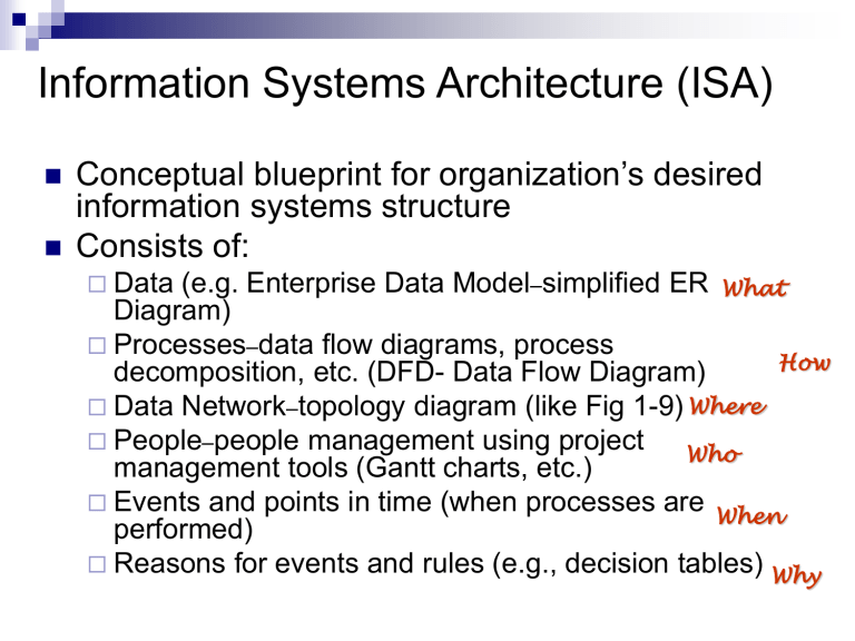
Information Systems Architecture (ISA)
Conceptual blueprint for organization’s desired information systems structure
Consists of:
Data (e.g. Enterprise Data Model – simplified ER
Diagram)
What
Processes – data flow diagrams, process decomposition, etc. (DFD- Data Flow Diagram)
Data Network – topology diagram (like Fig 1-9) Where
How
People – people management using project management tools (Gantt charts, etc.)
Who
Events and points in time (when processes are performed)
When
Reasons for events and rules (e.g., decision tables)
Why
Data Flow Diagrams
Data flow diagrams (DFDs) are graphical aids that describe an information system
DFDs represent a logical model that shows what a system does, not how it does it
Advantages:
freedom from committing to the technical implementation of the system too early.
Further understanding the interralatedness of systems and subsystems.
communicating current system knowledge to users
.
Data Flow Diagrams
Data flow diagram symbols
Four basic symbols
Process
Data flow
Data store
External entity
External entities
Process
Data flows
Data store
Data Dictionary
Develop Enterprise Model
Functional decomposition
Iterative process breaking system description into finer and finer detail
Enterprise data model
Planning matrixes
Describe interrelationships between planning objects
Figure 2-2 Example of process decomposition of an order fulfillment function (Pine Valley Furniture)
Decomposition = breaking large tasks into smaller tasks in a hierarchical structure chart
Higher priority business function-to-data entity matrix
Spot missing entity
