Y.Nikulshin - Magnetic Simulations of HTS-FCL
advertisement
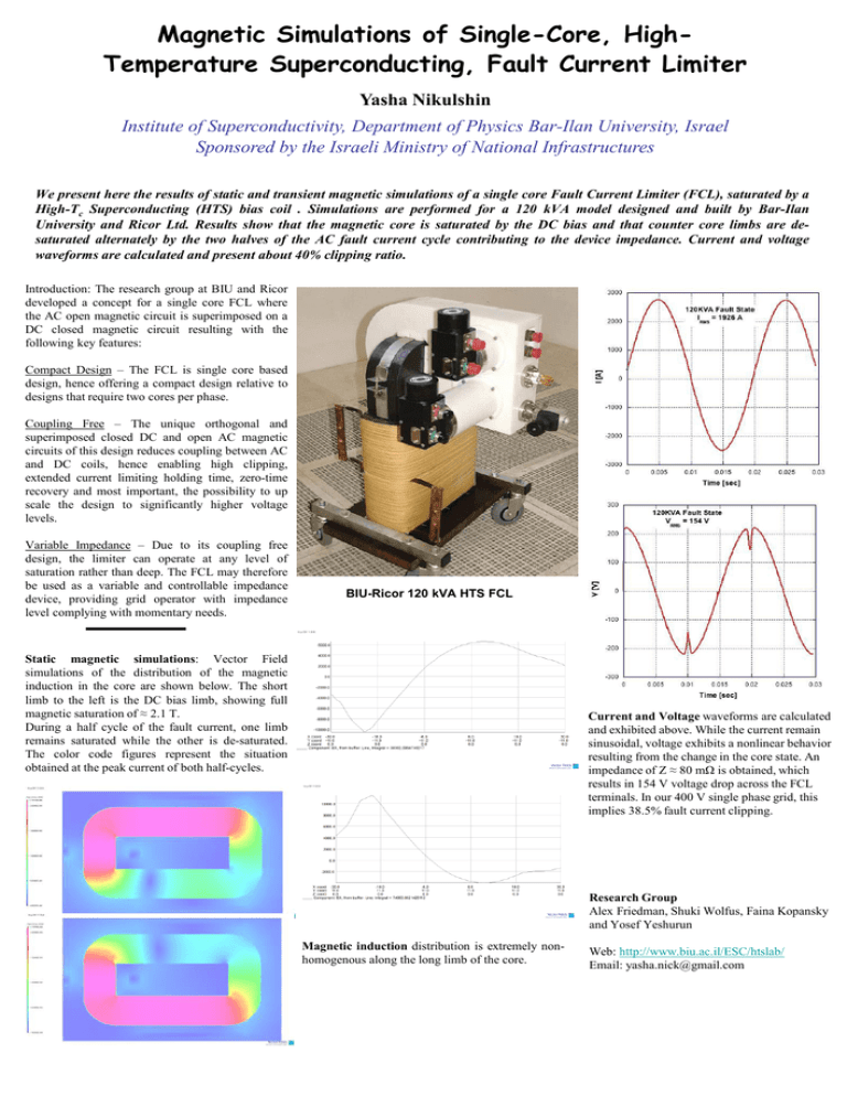
Magnetic Simulations of Single-Core, HighTemperature Superconducting, Fault Current Limiter Yasha Nikulshin Institute of Superconductivity, Department of Physics Bar-Ilan University, Israel Sponsored by the Israeli Ministry of National Infrastructures We present here the results of static and transient magnetic simulations of a single core Fault Current Limiter (FCL), saturated by a High-Tc Superconducting (HTS) bias coil . Simulations are performed for a 120 kVA model designed and built by Bar-Ilan University and Ricor Ltd. Results show that the magnetic core is saturated by the DC bias and that counter core limbs are desaturated alternately by the two halves of the AC fault current cycle contributing to the device impedance. Current and voltage waveforms are calculated and present about 40% clipping ratio. Introduction: The research group at BIU and Ricor developed a concept for a single core FCL where the AC open magnetic circuit is superimposed on a DC closed magnetic circuit resulting with the following key features: Compact Design – The FCL is single core based design, hence offering a compact design relative to designs that require two cores per phase. Coupling Free – The unique orthogonal and superimposed closed DC and open AC magnetic circuits of this design reduces coupling between AC and DC coils, hence enabling high clipping, extended current limiting holding time, zero-time recovery and most important, the possibility to up scale the design to significantly higher voltage levels. Variable Impedance – Due to its coupling free design, the limiter can operate at any level of saturation rather than deep. The FCL may therefore be used as a variable and controllable impedance device, providing grid operator with impedance level complying with momentary needs. (1) BIU-Ricor 120 kVA HTS FCL Static magnetic simulations: Vector Field simulations of the distribution of the magnetic induction in the core are shown below. The short limb to the left is the DC bias limb, showing full magnetic saturation of ≈ 2.1 T. During a half cycle of the fault current, one limb remains saturated while the other is de-saturated. The color code figures represent the situation obtained at the peak current of both half-cycles. Current and Voltage waveforms are calculated and exhibited above. While the current remain sinusoidal, voltage exhibits a nonlinear behavior resulting from the change in the core state. An impedance of Z ≈ 80 mΩ is obtained, which results in 154 V voltage drop across the FCL terminals. In our 400 V single phase grid, this implies 38.5% fault current clipping. Research Group Alex Friedman, Shuki Wolfus, Faina Kopansky and Yosef Yeshurun Magnetic induction distribution is extremely nonhomogenous along the long limb of the core. Web: http://www.biu.ac.il/ESC/htslab/ Email: yasha.nick@gmail.com
