Review Questions - Industrial Resources, Inc.
advertisement
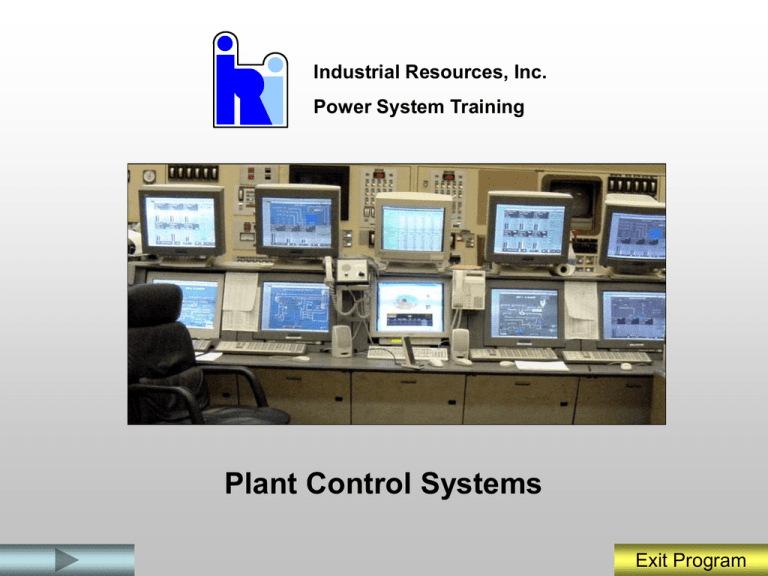
Industrial Resources, Inc. Power System Training Plant Control Systems Exit Program In this module we will: • • • • Describe the typical Distributed Control System capabilities. Describe how power plant processes are accessed and controlled from the DCS controllers. Describe how DCS control system diagrams are used to interpret control system loops. Describe basic Unit loading and control features. This presentation is designed to provide you the information you need to understand and operate the Distributed Control System. You should view all slides and read and study the information presented. Exit Program MAIN MENU To Start, Click on one of the buttons below You Should Start The Program In The System Function Section. System Function Process Control Control Diagrams Work Stations Unit Control Review Questions Review Questions Review Questions Review Questions Review Questions If you exit the program and want to re-start at a different section or want to see the review questions, click on the appropriate button. Exit Program Distributive Control System Function Exit Program The Distributive Control System controls plant systems and equipment. Motors Steam Turbine Valves Generator and Exciter Exit Program Plant Control System Overview The DCS System collects and stores three (3) types of data received from plant processes: • Analog data • Digital data • Calculated data Exit Program Analog Data Temperature Transducer Pressure Transducer Flow Transducer Exit Program Digital Data Motors “ON” Motor “OFF” Valve Closed Limit Switch Valves Open Exit Program Calculated Values Water Temperature Water Flow AIN AIN PID PID AOUT Valve Position Signal Temperature/Density Compensated Water Flow Compound Exit Program Provides Data Access Exit Program CRT Alarms Alarms Exit Program Allows for Control Exit Program Historical Data Retrieval Deaerator Storage Tank Level Trend Exit Program Control System Data Flowpath Exit Program Node Bus Exit Program Control Processors Exit Program Work Station Work Station Exit Program Work Station CRTs (Monitors) Trackball Keyboard and Annunciator Keypad Exit Program Communication Exit Program Types of Displays Several types of displays are accessible from the control system. These include: P&ID Displays Motor Control Displays Process Control Displays Exit Program P&ID Displays Exit Program Motor Control Displays Exit Program Process Control Displays Measured Bias Output Exit Program Review Questions What three types of data received from plant processes are collected and stored by the DCS? Review What is the typical origin of Analog data? Review What is the function of the “node” bus? Review Which type system display represents system piping and instrumentation? Review Exit Program Process Control Basics Exit Program Control Processor Exit Program Control Loops Include: • • • • Measured Variable (MEAS) Sensor Controller Final Control element. Exit Program Relay Control Start/Stop Controls Open/Close Controls Exit Program Modulating Control Water Temperature AIN PID Water Flow AIN PID AOUT Valve Position Signal Control Loop Controller Exit Program Control Processor Exit Program DCS Control Two (2) types of control signals route to and from the DCS System Controller: • Digital Signals (Zero and One) • Analog Signals (4 – 20 Ma) Exit Program Computer Logic Blocks There are several types of logic blocks used to convert analog signals to digital signals for use by the DCS. These include: • • • • • AIN Block AOUT Block CIN Block LLAG Block PID Block Exit Program AIN and AOUT Blocks AIN Temperature Transducer AOUT Valve Exit Program CIN Block CIN Breakers Exit Program Lead Lag (LL Block) Gland Exhaust Fans Select A LLAG Select B Exit Program PID Block 3-element Drum Level Feedwater Flow Steam Flow PID Valve Position Signal Feedwater Master Exit Program Compounds Water Temperature Water Flow AIN AIN PID PID AOUT Valve Position Signal Temperature/Density Compensated Water Flow Compound Exit Program Review Questions What is process control? Review What is an Algorithm? Review What two (2) types of control signals route to and from the DCS System Controller? Review What is a Compound? Review Exit Program Control Diagrams Exit Program Control Diagrams Control Diagrams provide the following types of information: • Control system component arrangement • Control system component function indicating the signal conditioning • Operating characteristics of the control system • Operator interface devices • Setpoints, transfer points, permissives, Alarms Exit Program Control Diagram Symbols The following types of control symbols are found on Control Diagrams: • • • • Transmitter and/or sensing elements Final Control Element/Operator Converters Signal Processors Exit Program Sensing Elements and Symbols PT LT Pressure Transducer Pressure Transmitter Level Sensors Level Transmitter FT Pitot Tubes Flow Transmitter Exit Program Final Control Element Valve Positioner Motor Controller Damper Positioner Hydraulic Coupling Controller Exit Program Converters • • • • • • • Current to digital converter (I/D) Thermocouple to digital converter (MV/D) Resistance to digital converter (R/D) Digital to current converter (D/I) Current to pneumatic converter (I/P) Contact to digital converter (C/D) Digital to contact converter (D/C) Exit Program Signal Processors • • • • Single digital input conversion true = 1 (CIN) Digital input conversion true = 0 (CIN) not Single analog input conversion (AIN) Analog output conversion (AOUT) Exit Program Control Diagram Symbols Summer Comparator Multiplier Averaging Exit Program Control Diagram Symbols Proportional Controller Derivative Rate Controller Integral/Reset Controller Multi-function Segment Characterizer Exit Program Control Diagram Symbols Time Function Characterizer Signal Selector Bias Unit Signal Limiter Exit Program Control Diagram Symbols Transfer or Trip Relay Switch Manual Output Driver Analog Signal Generator Exit Program Logic Gates and Truth Tables • • • • • Building Blocks of Digital Logic Most have 2 or more inputs Operate in Binary Low State is 0 Volts High State is 5 Volts Exit Program “AND” GATE Input 1 Output Input 2 “AND” Gate Input 1 Input 2 Output 0 0 0 0 1 0 1 0 0 1 1 1 Truth Table Exit Program “OR” GATE Input 1 Input 1 Input 2 Output 0 0 0 0 1 1 1 0 1 1 1 1 Output Input 2 “OR” Gate Truth Table Exit Program “NOT” GATE Input Outp ut “NOT” Gate Input Output 1 0 0 1 Truth Table Exit Program SET/RESET and TIME DELAY TD On SET/RESET TD Off TIME DELAY On/Off Exit Program Review Questions What types of information are provided on Control Diagrams? Review Name 3 types of sensing elements. Review Name 3 types of final control elements. Which type logic gate functions to reverse the logic state? Review Review Exit Program Work Station Environment CRTs (Monitors) Trackball Keyboard and Annunciator Keypad Exit Program Historical Trend/Retrieval Exit Program Operator Controllable Faceplates Exit Program Controller and Trend Graphic Deviation from Level Setpoint Level Setpoint Valve Output Percent/OPEN Exit Program Face Plate Upper Portion Controller Name Auto/Manual Soft Keys Exit Program Face Plate Lower Portion High and Low Markers Deviation from Level Setpoint Measured Variable Block Setpoint Output Signal Level Setpoint Valve Output Percent/OPEN Exit Program Additional Control Letters Exit Program Control Letters Letter Description A Indicates the block is in Automatic M Indicates the block is in Manual L Indicates the block is in local control/controlled by the operator R Indicates the block is remotely controlled/controlled internally by the control system T Indicates the block is tracking the output and trying to maintain setpoint Exit Program Control Block Values Exit Program Control Block Values Abbreviations Abbrevi ation Description MEAS Indicates the value of the measured variable. MEAS is in blue, the same color as the vertical Measured Variable bar. Measurement increments for the variable are provided. SPT Indicates the controller setpoint. SPT is in magenta, as is the vertical Setpoint Bar. The numerical representation for the setpoint is provided. BIAS If Bias control is available, there may be BIAS listed rather than SPT. OUT Indicates the controller output, with the actual value indicated. The OUT is represented in white, as is the vertical Output Bar. Exit Program Soft Keys Soft Keys Exit Program Soft Key Functions Alarm Acknowledge Key Block Detail Display Key Exit Program Soft Key Functions Up Arrow Key Down Arrow Key Exit Program Soft Key Functions Double Up Arrows Key Double Down Arrows Key Exit Program Soft Keys Box Key Side Arrows Exit Program Trend Graphs Exit Program Trend Graph Information Exit Program Trend Graphs Days Hours Minute s Second s Exit Program Trend Graphs Pause Bar Exit Program Alarm Display Alarm Display Date Time Alarm Desc. Engr Units Value Alarm Alarm Alarm Limit Type Priority ACK State Exit Program Alarm Display Screen Alarm Display Date Time Alarm Description Engineering Units Value at time of alarm Alarm Limit 050106 0807 MS temp Hi DegF 1015 050106 0803 MS temp Hi DegF 1010 Alarm Type Alarm Priority ACK State 1010 2 UnAck 1010 2 Ack Exit Program Alarm Priority • • • • • Priority 1 Priority 2 Priority 3 Priority 4 Priority 5…. Exit Program Alarm Priority (typical Definitions) • • • • • Priority 1 - when active, alerts the operator to a Loss of the Unit or unsafe operating condition. This priority alerts the operator to a time-critical condition for which immediate action is required to prevent a loss of the unit, operating capacity, personal injury or which may result in equipment damage. Priority 2– when active, alerts the operator to a condition which results in a loss of unit load (MW). This priority alerts the operator to a condition requiring immediate investigation and operator action to prevent a loss of generation, an environmental exceedance, or impending condition degradation to a Priority 1. Priority 3 – when active, alerts the operator to a condition that can result in the loss of a major piece of equipment. This priority requires the operator to monitor the condition/equipment and take corrective action and to report the condition to the associated maintenance group as required. Priority 4 – when active, alerts the operator to a condition that can result in the loss of a piece of minor equipment. Typically this alarm occurs on loss of process feedback or in the event of a disparate device signal (bad quality). Priority 5– may be reserved for Maintenance Alarms Exit Program Alarm Display • • • • • Most Recent Alarms Display New Alarms Display Unacknowledged Return Alarms Display Acknowledged Alarms Display Alarm History Display Exit Program Review Questions Which portion of the control system collects, stores, processes and archives process data from the control system to provide data for trends, logs, and reports? Review What types of information/controls can be found on the sections of the Group Display? Review Exit Program Basic Unit loading and Control Exit Program Megawatt Demand Signal Exit Program Unit Demand Limiter Exit Program Unit Demand Limiter Exit Program Runbacks Exit Program LMCC Exit Program Operator Adjustable Setpoints Exit Program LMCC Controls Exit Program Control Modes Exit Program LMCC Controls Exit Program Review Questions What type of control between the boiler and turbine/generator produces the best load response? What information is used to set upper and lower megawatt limits on the Control System? What is the function of the LMCC “HOLD” Button? Review Review Review After you have answered these question you may exit the program, or continue to to the next 6 slides for a list all the IRI Maintenance Modules which are available. Exit Program Electrical Maintenance Modules • • • • • • • • • • • • • • • • • • • • High Intensity Discharge Lighting (EM01) Conduit Bending (EM02) Battery System (EM03) Medium Voltage Overhead Distribution Lines (EM04) Medium Voltage Underground Distribution Lines (EM05) (AV) Multiamp SR90 Relay Tester (EM06 Protective Relays (EM07) Kilowatt-hour Meters (EM08) Emergency Generator EM09) Liquid Filled Transformer (EM10) Medium Voltage Switchgear (EM11) Primary Current Injection (AVO) (EM12) Medium voltage Drawout Circuit Breaker (EM13) Medium Voltage Vacuum Circuit Breaker (EM14) Low Voltage Drawout Circuit Breaker (EM15) Power Quality Monitoring Equipment (EM16) Automatic Transfer Switches (EM17) Manual Wrap-Around Bypass Switches (EM18) Cable Splicing and Termination (EM19) Cable Pulling and Installation (EM20) Exit Program I & E Maintenance Modules • • • • • • • • • • • • • • • • • • • • Hart Communicator (IE01) Protective Relays (IE02) DC Motors (IE03) Three-Phase Motors (IE04) Cable and Wire Terminations (IE05) Low Voltage Breakers (IE06) Medium Voltage Breakers (IE07) Variable Frequency Drives (IE08) Allen Bradley PLC Model 5/30 (IE09) Station Batteries (IE10) Bench Grinder (IE11) Drill Press (IE 12) Pressure Switch (IE-13) Emission Monitoring Equipment (IE14) Flow Transmitters (IE15) Pressure Transmitters (1E16) Level Transmitters (IE17) Temperature Transmitters (IE18) Valve Pneumatic Positioners (IE19) Electrical Positioners (IE20) Exit Program Mechanical Maintenance Modules • • • • • • • • • • • • • • • Air Compressor Maintenance (MM01) Bobcat-Loader (MM02) Bobcat-Sweeper (MM03) Bobcat-Backhoe (MM04 Pipe Locator (MM05) Explosion Meter (MM06) Valves (MM07) Bearings and Seals (MM08) Pedestal Grinders (MM09) Metal Cutting Band Saw (MM10) Drill Press (MM11) Steam Trap (MM12) Portable Threader (MM13) Hydraulic Steel Pipe Cutters (MM14) Ultrasonic Thickness Gauge (MM15) • • • • • • • • • • • • • • • Coupling and Shaft Alignment (MM16) Oxy Acetlene Cutting (MM17) Water Meter Testing (MM18) Centrifugal Pumps *(MM19) Silver Solder (MM20) Pipe Cutter (MM21) Tubing Cutter (MM22) Sewer Auger (MM23) Backhoe Jackhammer (MM24) Dump Truck (MM25) Fire Hydrant (MM26) Trench Shoring (MM27) Water Main Repair/Replacement (MM28) Backhoe Loader (MM29) Truck Mounted Valve Operator (MM30) Exit Program Machine Shop Modules • • • • • • • • • • • Manual Lathe “DRO” (MS01) Manual Mill “DRO” (MS02) Automatic Surface Grinder (MS03) Overhead Hoist (MS04) Bolt Threading Machine (MS05) Sander MS 06 Shears (MS07) Sheet Metal Brake (MS 08) Radial Drill (MS09) Computer Controlled Mill “CNC” (MS-10) Dry Blast Cabinet (MS-11) Presses/Floor and Arbor (MS12) Exit Program System Maintenance Modules • Single-Stage Centrifugal Pumps (SM06) • Soot Blower Maintenance (SM-07) • Oxy-Acetylene Cutting (SM08) • Pulverizer Maintenance MPS 89 (SM09) • Air Compressor Maintenance (SM10) • Conveyor Belt Maintenance (SM12) • Chemical Feed Pump (SM13) • Multi-stage Vertical Condensate Pump (SM-14) • FD Fans (SM-15) • Fuel / Coal Feeders (SM-16) • Gauge Glass Maintenance (SM-17) • Heat Exchangers (SM-18) • Dry Vacuum Exhauster Maintenance (SM19) • Riley Ball Tube Mill Maintenance (SM20) Exit Program Industrial Resources, Inc. A Training Services Company For More Information about our training Programs please contact IRI Sales at 228 392 3973 or Indresinc@aol.com ExitExit Program Program Plant Control System Overview The DCS System collects and stores three (3) types of data received from plant processes: • Analog data • Digital data • Calculated data Return to Review Questions Analog Data Temperature Transducer Pressure Transducer Flow Transducer Return to Review Questions Node Bus Return to Review Questions P&ID Displays Return to Review Questions Process Control Basics Return to Review Questions Control Processor Return to Review Questions DCS Control Two (2) types of control signals route to and from the DCS System Controller: • Digital Signals (Zero and One) • Analog Signals (4 – 20 Ma) Return to Review Questions PID Block 3-element Drum Level Feedwater Flow Steam Flow PID Valve Position Signal Feedwater Master Return to Review Questions Control Diagrams Control Diagrams provide the following types of information: • Control system component arrangement • Control system component function indicating the signal conditioning • Operating characteristics of the control system • Operator interface devices • Setpoints, transfer points, permissives, Alarms Return to Review Questions Sensing Elements and Symbols PT LT Pressure Transducer Pressure Transmitter Level Sensors Level Transmitter FT Pitot Tubes Flow Transmitter Return to Review Questions Final Control Element Valve Positioner Motor Controller Damper Positioner Hydraulic Coupling Controller Return to Review Questions “NOT” GATE Input Outp ut “NOT” Gate Input Output 1 0 0 1 Truth Table Return to Review Questions Historical Trend/Retrieval Return to Review Questions Controller and Trend Graphic Deviation from Level Setpoint Level Setpoint Valve Output Percent/OPEN Return to Review Questions Basic Unit loading and Control Return to Review Questions Megawatt Demand Signal Return to Review Questions LMCC Controls Return to Review Questions
