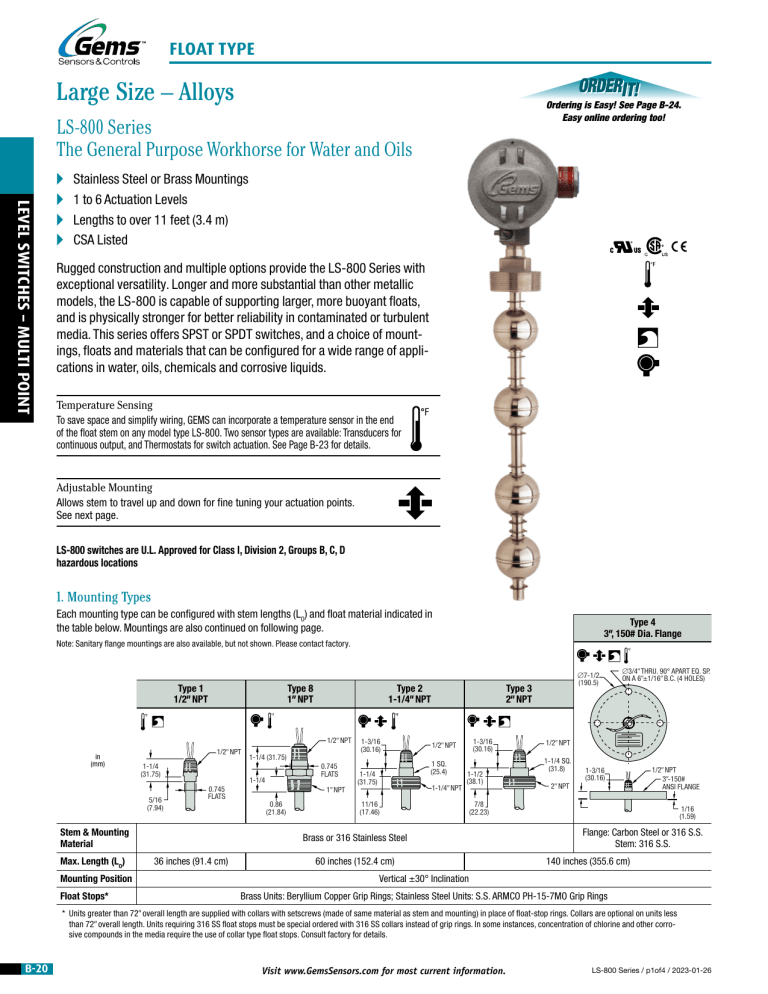
FLOAT TYPE Large Size – Alloys Ordering is Easy! See Page B-24. Easy online ordering too! LS-800 Series The General Purpose Workhorse for Water and Oils LEVEL LEVEL SWITCHES SWITCHES -–SINGLE MULTI POINT POINT A A A A Stainless Steel or Brass Mountings 1 to 6 Actuation Levels Lengths to over 11 feet (3.4 m) CSA Listed Rugged construction and multiple options provide the LS-800 Series with exceptional versatility. Longer and more substantial than other metallic models, the LS-800 is capable of supporting larger, more buoyant floats, and is physically stronger for better reliability in contaminated or turbulent media. This series offers SPST or SPDT switches, and a choice of mountings, floats and materials that can be configured for a wide range of applications in water, oils, chemicals and corrosive liquids. Temperature Sensing To save space and simplify wiring, GEMS can incorporate a temperature sensor in the end of the float stem on any model type LS-800. Two sensor types are available: Transducers for continuous output, and Thermostats for switch actuation. See Page B-23 for details. Adjustable Mounting Allows stem to travel up and down for fine tuning your actuation points. See next page. LS-800 switches are U.L. Approved for Class I, Division 2, Groups B, C, D hazardous locations 1. Mounting Types Each mounting type can be configured with stem lengths (LO) and float material indicated in the table below. Mountings are also continued on following page. Type 4 3", 150# Dia. Flange Note: Sanitary flange mountings are also available, but not shown. Please contact factory. Type 1 1/2" NPT Type 8 1" NPT Type 2 1-1/4" NPT 1/2" NPT in (mm) 1/2" NPT 1-1/4 (31.75) 5/16 (7.94) Mounting Position Float Stops* 0.745 FLATS 1-1/4 0.745 FLATS Stem & Mounting Material Max. Length (LO) 1-1/4 (31.75) 1" NPT 0.86 (21.84) 1-3/16 (30.16) 1-3/16 (30.16) 1/2" NPT 1 SQ. (25.4) 1-1/4 (31.75) 1-1/4" NPT 1-1/2 (38.1) 11/16 (17.46) ∅3/4" THRU. 90° APART EQ. SP. ON A 6"±1/16" B.C. (4 HOLES) 1/2" NPT 1-1/4 SQ. (31.8) 2" NPT 1-3/16 (30.16) 1/2" NPT 3"-150# ANSI FLANGE 7/8 (22.23) Brass or 316 Stainless Steel 36 inches (91.4 cm) ∅7-1/2 (190.5) Type 3 2" NPT 60 inches (152.4 cm) 1/16 (1.59) Flange: Carbon Steel or 316 S.S. Stem: 316 S.S. 140 inches (355.6 cm) Vertical ±30° Inclination Brass Units: Beryllium Copper Grip Rings; Stainless Steel Units: S.S. ARMCO PH-15-7MO Grip Rings * Units greater than 72" overall length are supplied with collars with setscrews (made of same material as stem and mounting) in place of float-stop rings. Collars are optional on units less than 72" overall length. Units requiring 316 SS float stops must be special ordered with 316 SS collars instead of grip rings. In some instances, concentration of chlorine and other corrosive compounds in the media require the use of collar type float stops. Consult factory for details. B-20 Visit www.GemsSensors.com for most current information. LS-800 Series / p1of4 / 2023-01-26 FLOAT TYPE LS-800 Series – Continued Type 5 External Mounting units are ideal for tanks with limited access to tops or bottoms. LS-800-A Series Adjustable Mounting Type 5 External Mount, Multi-Station 0-RING Available for LS-800 Series Mounting Types 2, 3 and 4. 1/2" FNPT 2-1/4"-12 UNF-2A THR'D 1-3/4 (44.5) UNIT LENGTH LO+2" N.C. 2 (50.8) in (mm) 3/4" NPT PORTS (2×) Housing Material Brass 316 Stainless Steel Stem & Mounting Material Brass 316 Stainless Steel 3/4" NPT Maximum Length (LO) 120 inches (305 cm) Float Stops* Beryllium Copper MOUNTING MAX. ADJUST FLOAT STOP Note: Maximum overall length is limited to 72" with this option. N.O. Port Sizes UNION Special cinch-nut on mounting allows stem to travel up or down for fine tuning the actuation points. The extent of adjustment depends on unit length and distance from mounting to highest float stop. When ordering, specify “LS-800-A” as Series Type. 2-5/8 DIA. REF. (66.7) LO±1/16" UNIT STEM ADJUSTED UPWARD S.S. ARMCO PH-15-7MO LEVEL LEVEL SWITCHES SWITCHES -–SINGLE MULTI POINT POINT 1. Mounting Types – continued Intrinsically-Safe Relays Using Gems SAFE-PAK® relays and barriers, these switches provide automatic refills/pumpdown and are intrinsicallysafe without explosion-proof housing and piping. * Units greater than 72" overall length are supplied with collars with setscrews (made of same material as stem and mounting) in place of float-stop rings. Collars are optional on units less than 72" overall length. Units requiring 316 SS float stops must be special ordered with 316 SS collars instead of grip rings. In some instances, concentration of chlorine and other corrosive compounds in the media require the use of collar type float stops. Consult factory for details. 2. Float Types A single float type is selected for use at all actuation points. Be sure, by reviewing the table below, that the desired float is compatible with the Mounting Type selected in Step 1. Float Material Buna-N Compatible Mounting Types Float Dimensions See Section L 1, 2, 3, 4, 8 2 1-5/16 (33.3) in (mm) 1-1/16 (27) DIA. Part Number 1, 3, 4, 5 1-13/16 (46.0) 1-3/4 (44.5) 1-1/4 (31.8) DIA. 253644 316 Stainless Steel 3, 4, 5 (Units >72") 26032 1-13/16 (46.0) 1-7/8 (47.6) DIA. 1, 3, 4, 5 (Units ≤72") 2-3/32 (53.3) 24864 14569 Min. Media Specific Gravity 0.55 0.75 0.55 253644 26032 0.55 15666 5 0.75 24864 150 psi (10.3 bar) Brass 138935 0.75 0.80 14569 15666 138935 750 psi (51.7 bar) 300 psi (20.7 bar) 180 psi (12.4 bar) 150 psi (10.3 bar) 316 S.S. 1.63 (41.4) MAX. DIA. Float Part Number 10558 4 Mounting Type 2-1/16 (52.4) −40°F to +300°F (−40°C to +149°C) Maximum Pressure Ratings Chart 1, 2, 3 1.36 (34.6) 2-11/16 (68.3) 2-1/16 (52.4) Water: to 180°F (82°C) Oil: −40°F to +230°F (−40°C to +110°C) Operating Temperature 1, 3, 4 2 (50.8) 1-7/8 (47.6) DIA. 10558 3, 4, 5 (Units >72") 180 psi (12.4 bar) 100 psi (6.9 bar) @ 70°F (21°C) 150 psi (10.3 bar) 750 psi (51.7 bar) 300 psi (20.7 bar) 120 psi (8.3 bar) Review the Compatible Mounting Type row in the “Float Types” table above this matrix for produceable mounting/float combinations. Not all combinations implied by this Pressure Rating Chart are possible or recommended. LS-800 Series / p2of4 / 2023-01-26 Visit www.GemsSensors.com for most current information. B-21 FLOAT TYPE LEVEL LEVEL SWITCHES SWITCHES -–SINGLE MULTI POINT POINT 3. Electrical Specifications Wiring Color Code Switch (N.O. or N.C.): SPST: 20 VA or 100 VA SPDT: 20 VA Tinted area designates U.L. Recognized wiring configurations. SPST Switches Lead Wires: 18 AWG, 24" L., Polymeric (except as noted in Wiring Color Code chart at right). Approvals: LS-800 Series switches are U.L. Recognized – File No. E45168; CSA Listed – File No. 30200 Typical Wiring Diagrams For clarity, only two actuation levels are shown in each group diagram. GROUP I SPST GROUP II SPST GROUP III SPDT GROUP IV SPDT SPDT Switches 20 VA Wiring Group I Group II Group III Group IV Com. Wire Black None Black None NO/NC SW. Com. NO/NC NO NC SW. Com. L1 Red Red Red Red Wh/Red Red L2 Yellow Yellow Yellow Yellow Wh/Yel Yellow L3 Blue Blue Blue Blue Wh/Blue Blue NO NC Wh/Red Wh/Blk/Red Wh/Yel Wh/Blk/Yel Wh/Blue Wh/Blk/Blu L4 Brown Brown Brown Brown Wh/Brn Brown Wh/Brn Wh/Blk/Brn L5 Orange Orange Orange Orange Wh/Orn Orange Wh/Orn Wh/Blk/Orn L6 Gray Gray Gray Gray Wh/Gra Gray Wh/Gra Wh/Blk/Gra Notes: 1. Non-U.L. Recognized units (white areas) use 22 AWG, 24" L., PTFE Lead wires. 2. Units with 100 VA switches are not U.L. Recognized or CSA Listed. 3. See “Electrical Data” on Page X-5 for more information. 4. Actuation Level Dimensions Switch actuation levels are determined following the guidelines below. Actuation Levels* ‑ Typical All units 72" or less LO with Stainless Steel or Buna-N floats. Also any unit over 72" LO with Buna-N floats: L6 A = 1-1/2" (38.1 mm) minimum distance to highest level (2", Type 5 only). L5 B = 2" (50.8 mm) minimum distance from end of unit to lowest level. A C = 3" (76.2 mm) minimum distance between levels. L4 D = 1/4" (6.3 mm) minimum distance between actuation levels (Note: One float for two levels can be used only when low level is N.C. dry and high level is N.O. dry). LO (LENGTH OVERALL) L3 Types 1, 3, 4, and 5 units with stainless steel float, Part Number 15666: D A = 1-5/8" (41.3 mm) minimum distance to highest level (2", Type 5 only). L2 B = 2-1/2" (63.5 mm) minimum distance from end of unit to lowest level. C C = 4" (101.6 mm) minimum distance between level. L1 D = 1/4" (6.3 mm) minimum distance between actuation levels (Note: One float for two levels can be used only when low level is N.C. dry and high level is N.O. dry). B * Actuation level distances and LO (overall unit length) are measured from inner surfaces of mounting plug or flange. ** Length Overall LO = L1 + Dimension B. See Mounting Types for Maximum Length values. B-22 Notes: 1. A, B and C dimensions based on a liquid specific gravity of 1.0. 2. One float for two levels can be used only when 20 VA switch is used. 3. Actuation levels are calibrated on descending fluid level, with water as the calibrating fluid, unless otherwise specified. 4. Tolerance on actuation levels is ±1/8" (3.2 mm). 5. TH (Temperature option) makes “B” dimension a minimum of 2.75" (69.8 mm). Visit www.GemsSensors.com for most current information. LS-800 Series / p3of4 / 2023-01-26 OPTIONAL TEMPERATURE SENSORS Optional Integrated Temperature Sensors °F A Compatible with LS-700 and LS-800 Series Units A Thermostat Switches or Thermistor Versions Advantages of integrated temperature sensors: Control heating elements and liquid level with a single sensor. LEVEL LEVEL SWITCHES SWITCHES -–SINGLE MULTI POINT POINT • Space Saving. • Fewer intrusions into the tank. • Electrical wiring emanates from a single source – eliminate multiple conduits. • Economical – typically less expensive than separate sensors. Thermistor for Continuous Indication – TM-800 and TM-700 A Excellent repeatability T Value: 10,000 ohms @ 77°F (25°C) Tolerance: ±0.2°C from 32°F to 158°F (0°C to 70°C) Operating Temperature: 302°F (150°C), Max. Alpha @ 25°C: −4.39%/°C Dissipation Constant: 1 mW/°C in Still Air; 8mW/°C in Oil Bath. GROUP I How to Order Temperature thermistors are available on LS-700 Series units with up to three actuation levels, and on LS-800 Series units with up to five actuation levels. To have thermistor added, order model TM-800 or TM-700. T GROUP II Note: This option is not CE Approved. Thermostat for Switch Actuation • Standard Settings from 100°F to 200°F. • Open or close switch on increasing temperature. Use these switches to set off High/Low temperature alarms. Or, combine with GEMS relays to control tank heating and cooling, motor-operated valves, etc. To designate the thermostat switch option, order model TH-700 or TH-800. Also specify the choice from selections A, B and C below. A. Switch Rating: For LS-800 Series: 6A/120V, 4A/240V, 100VA (non-inductive). For LS-700 Series: 2.6A/120V (inductive). B. Contact Operation on Increasing Temperature: “Opens” when Set Point reached or “Closes” when Set Point reached. C. Standard Temperature Set Point (±7.2°F; ±4°C): 100°F (37.7°C), 125°F (51.6°C), 150°F (65.6°C), 175°F (79.4°C), 200°F (93.3°C) Notes: 1. Other temperature settings and tolerances available; 25 piece minimum order quantity applies. Please call GEMS Sensors Inc. for more information. 2. This option is not CE Approved. LS-800 Series / p4of4 / 2023-01-26 TEMPERATURE SENSOR ASSEMBLY BOTTOM OF UNIT Note: End of unit stem must be submerged a minimum of 2-3/4" for level switch actuation. Typical Wiring Diagram BLACK BLACK RED RED GREEN GREEN GROUP I Visit www.GemsSensors.com for most current information. GROUP II B-23
