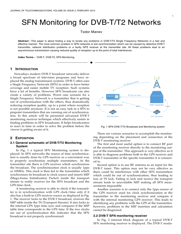
JOURNAL OF TELECOMMUNICATIONS, VOLUME 29, ISSUE 2, FEBRUARY 2015 1 SFN Monitoring for DVB-T/T2 Networks Todor Manev Abstract—This paper is about finding a way to locate any problems in DVB-T/T2 Single Frequency Networks in a fast and effective manner. The most common problem in SFN networks is lost synchronization which can be caused by defective DVB-T transmitter, network distribution problems or a faulty GPS receiver at the transmitter site. All these problems lead to an asynchronous transmission causing reduced quality of reception up to the point of total interference. Index Terms— DVB-T, DVB-T2, SFN Monitoring. —————————— u —————————— 1 INTRODUCTION Nowadays modern DVB-T broadcast networks deliver a broad spectrum of television programs and have replaced the analog transmission systems. DVB-T often uses a Single Frequency Network (SFN) in order to have better coverage and easier mobile TV reception. Such systems have a lot of benefits. However SFN broadcasts can also create a variety of problems. Worst case scenario for a Single Frequency Network is a transmitter that is getting out of synchronization with the others, thus dramatically reducing reception quality, up to a point where reception is not possible anymore. It is not an easy task in a SFN to pinpoint transmitters that are running out of synchronization. In this article will be presented advanced DVB-T monitoring receiver technique which effectively assists in finding problems in SFN broadcasts. It helps broadcasters to react in time in order to solve the problem before the viewer is getting aware of it. 2 EXPOSITION 2.1 General schematic of DVB-T/T2 Monitoring System In Fig. 1 a typical SFN Monitoring system is displayed. In SFN networks the source of time synchronization is usually done by GPS receiver as a convenient way to properly synchronize multiple transmitters. At the transmitter site there is GPS receiver which synchronizes the broadcast. The synchronization clock is usually 1pps or 10MHz. This clock is then fed to the transmitter which synchronizes its broadcast to clock source and inserts MIP (Mega-frame Initialization Packet) inside the transport stream to notify receiver for the SFN broadcast and the GPS time clock. A monitoring receiver is able to check if the transmitter is in synchronization with GPS clock/time only if it also has a built-in GPS receiver source as displayed in Fig. 1. The receiver locks to the DVB-T broadcast, receives the MIP table inside the TS (Transport Stream). It also locks to the internal GPS 1pps time sync and compares if the MIP table time corresponds to the GPS time. If the two clocks are out of synchronization this indicates that the SFN broadcast is not properly synchronized. Fig. 1 SFN DVB-T/T2 Broadcast and Monitoring system There are various scenarios to accomplish the monitoring depending on the placement and connection of the DVB-T monitoring receiver. The first and most useful option is to connect RF port of the monitoring receiver directly to the monitoring output of the transmitter. This approach is very effective as it is able to diagnose problems both in the GPS receiver and DVB-T transmitter of the specific transmitter it is connected to. Second option is to use RF antenna as an input for the DVB-T tuner. This option may not be very effective as there could be interference with other SFN transmitters which could be out of synchronization, thus leading to loss of TS lock. Failing to lock and receive the transport stream leads to unavailable MIP making all SFN measurements impossible. Another scenario is to connect only the 1pps source of the GPS receiver used for clock synchronization at the transmitter to the monitoring receiver and compare it with the internal monitoring GPS receiver. This leads to identifying any problems with the GPS of the transmitter, however, problems in the MIP insertion and calculation cannot be diagnosed. 2.2 DVB-T SFN monitoring receiver In Fig. 2 internal block diagram of a typical DVB-T SFN monitoring receiver is displayed. The DVB-T modu- 2 lated signal is fed to the RF input of the DVB-T tuner which demodulates the COFDM signal and the received TS is then fed to CPU for processing using transport stream interface. Then MIP table is extracted and the Synchronization Time Stamp (STS) inside the packet is compared to the GPS pulse received in the GPS receiver connected to the CPU. Fig. 2 SFN DVB-T/T2 Monitoring Receiver System Synchronization and transmission information sent by transmitters are inserted into one TS packet called MIP packet (or table). DVB normalized its PID to 0x15. The norm which specified MIP insertion defined a new group of packet, namely megaframe. The size of the megaframe depends on the code rate, as well as the constellation used. The SFN Adapter forms a megaframe (n TSpackets), corresponding to 8 frames (or 2 super-frames) in 8k mode, 16 frames (or 4 super-frames) in 4k mode, and 32 frames (or 8 super-frames) in 2k mode. The MIP inserter will insert exactly one MIP packet per megaframe (with dedicated 0x15 PID). The position of the MIP packet within the megaframe is signaled by the field 'pointer'. [1] 2.3 Algorithm used to calculate SFN synchronization timestamp drift In Fig. 3 a schematic of the relationship between the timestamp in the MIP table and the GPS 1pps is displayed. This shows how the synchronization timestamp (STS) is calculated. Define T=0 as when 1 pps pulse goes high and reference all timestamps relative to this. Use internal CPU clock timer 1MHz (gives accuracy of +/- 1us) or higher to accurately timestamp the drift. Receive all MIP packets. Use the pointer field from the MIP to identify which packet is the start of the next (M+1) megaframe. Timestamp - using local timer - the reception of the first (M+1) mega-frame packet. The timestamp is relative to the T=0 point in time occurring as the 1pps pulse goes high. Call this value ACTUAL. Extract the corresponding fields from the MIP packet and call it IDEAL. This is a calculated value and represents the time from when the 1pps pulse goes high to when the start of the (M+1) mega-frame should be transmitted out of the antenna of each transmitter tower. ACTUAL is larger than IDEAL in a real-life system due to the transmission delay from the transmitter antenna output to the COFDM demodulator antenna input. A second delay factor is the delay in the COFDM demodulator stage of the DVB-T tuner which is internally calibrated in the device [4]. If the GPS sync of the transmitter is failing then the transmitter will slowly start to drift out. We will see this as a gradual change in (ACTUAL-IDEAL). This is causes an alarm condition User specifies alarm criteria as a number (units: time) that the absolute value of (ACTUAL – IDEAL) difference should stay within. For example: Generate alarm if ABS (ACTUAL – IDEAL) > 10 us. The alarms are logged inside the DVB-T Monitoring receiver and can be forwarded as SNMP Trap or e-mail. In Fig. 4 configuration table of SFN related alarms is displayed [3]. Minimum and maximum time of impulse response could be set depending on the placement of the receiver. Also maximum SFN impulse response drift could be configured this is the absolute maximum deviation of the impulse response value. It is also very useful to have alarms in the monitoring receiver if there is no MIP table inside the transport stream or no GPS lock, which makes SFN measurement of the impulse response impossible. Fig. 4 SFN alarms configuration table in embedded web site Fig. 3 Megaframe/GPS pulse timing relationship [2] In Fig. 5 the final result of the SFN monitoring is displayed. The SFN impulse response is calculated using the timestamp inside the MIP table and the timestamp from 3 the built in GPS receiver [3]. This also makes it possible to estimate the proximity of the transmitter to the monitoring device if RF antenna feed is used. If the SFN measurement is done using the monitoring RF output port of the transmitter (direct feed) this value should be 0uS. The distance to the transmitter is calculated using the SFN Impulse Response (uS) * 300 meters due to the speed of light with which the broadcasted wave travels from the transmitter to the receiver. coverage (strong Inter-carriers interferences). The use of good monitoring equipment is vital in finding and solving such problems. Timely discovery of any temporary or permanent problems in the SFN synchronization is very important for broadcasters that wish to supply faultless round-the-clock service to their clients. In this article we have shown a possible approach for creating and implementing such device. ACKNOWLEDGMENTS Fig. 5 SFN Measurements for one carrier view in embedded web site It is also useful if the monitoring receiver can do measurements for multiple DVB-T carriers using roundrobin check of each selected frequency. The approximate time needed for one carrier is 20 seconds as the receiver needs to tune and lock to the specific frequency monitored. Needs to decode and timestamp the MIP tables for this period and thus calculate the impulse response for each MIP. After that it calculates the drift of the impulse response and checks it with the configured thresholds. Besides these measurements also some RF measurement are performed like level, CNR (carrier to noise ratio), MER (Modulation Error Rate), CBER (Channel Bit Error Rate), and VBER (Viterbi Error Rate). In Fig. 6 the final result of the SFN and RF monitoring is displayed. This HTML table is automatically refreshed to show any changes or alarms that arise. In yellow the currently monitored carrier is displayed all values that are out of boundaries are displayed in red, in Fig. 6 all values are OK [3]. Fig. 6 SFN and RF monitoring for multiple DVB-T carriers 3. CONCLUSION Optimizing spectrum and bandwidth is made possible with Single Frequency Network topology: all the transmitters will radiate synchronously based on information provided by Single Frequency Network (SFN) adapter [5]. The more accurate SFN synchronization provided, the more precise RF coverage is. It is to be noted an inaccuracy of frequency synchronization will result in very bad RF The present document has been produced with the financial assistance of the European Social Fund under Operational Programme “Human Resources Development”. The contents of this document are the sole responsibility of “Angel Kanchev” University of Ruse and can under no circumstances be regarded as reflecting the position of the European Union or the Ministry of Education and Science of Republic of Bulgaria. Project No BG051PO001-3.3.06-0008 “Supporting Academic Development of Scientific Personnel in Engineering and Information Science and Technologies” REFERENCES [1] [2] [3] [4] [5] [6] ETSI TR 101 191 V1.4.1, Digital Video Broadcasting (DVB); DVB megaframe for Single Frequency Network (SFN) synchronization, 2004. ETSI TR 101 290 V1.2.1, Digital Video Broadcasting (DVB), Measurement guidelines for DVB systems, 2001. http://www.kvarta.net/DVB_MONITOR_A_C_T http://www.bridgetech.tv/pdf/sfn-drift-a.pdf http://www.enensys.com/documents/whitePapers/ENENSYS%20T echnologies%20-%20Single_frequency_network%20Overview.pdf http://www.2wcom.com/fileadmin/redaktion/dokumente/Produkt e/DVB-T_DTT_SFN_White_Paper Todor Manev received his B.S. and M.S. in Informatics from Sofia University in 2007 and 2010. During 2010, he was Technical Student in CERN, Geneva participating in LHC Computing Grid project. Since 2013 he started working on his PhD in Technical University, Gabrovo in Telecommunications Systems Monitoring, working on various projects regarding FM, DVB-T/C/S/S2/T/T2 monitoring. He is now with Kvarta Soft, Ltd.


