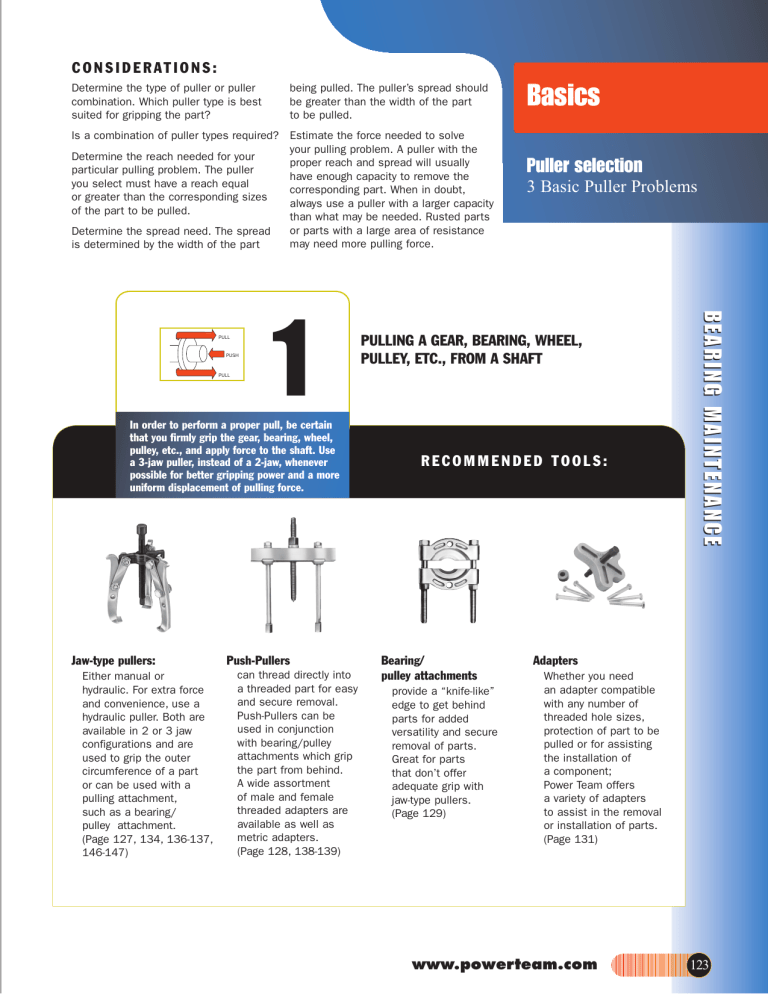
C O N S I D E R AT I O N S : Determine the type of puller or puller combination. Which puller type is best suited for gripping the part? being pulled. The puller’s spread should be greater than the width of the part to be pulled. Is a combination of puller types required? Estimate the force needed to solve your pulling problem. A puller with the Determine the reach needed for your proper reach and spread will usually particular pulling problem. The puller have enough capacity to remove the you select must have a reach equal corresponding part. When in doubt, or greater than the corresponding sizes always use a puller with a larger capacity of the part to be pulled. than what may be needed. Rusted parts or parts with a large area of resistance Determine the spread need. The spread may need more pulling force. is determined by the width of the part PUSH PULL 1 In order to perform a proper pull, be certain that you firmly grip the gear, bearing, wheel, pulley, etc., and apply force to the shaft. Use a 3-jaw puller, instead of a 2-jaw, whenever possible for better gripping power and a more uniform displacement of pulling force. Jaw-type pullers: Either manual or hydraulic. For extra force and convenience, use a hydraulic puller. Both are available in 2 or 3 jaw configurations and are used to grip the outer circumference of a part or can be used with a pulling attachment, such as a bearing/ pulley attachment. (Page 127, 134, 136-137, 146-147) Push-Pullers can thread directly into a threaded part for easy and secure removal. Push-Pullers can be used in conjunction with bearing/pulley attachments which grip the part from behind. A wide assortment of male and female threaded adapters are available as well as metric adapters. (Page 128, 138-139) Puller selection 3 Basic Puller Problems PULLING A GEAR, BEARING, WHEEL, PULLEY, ETC., FROM A SHAFT RECOMMENDED TOOLS: Bearing/ pulley attachments provide a “knife-like” edge to get behind parts for added versatility and secure removal of parts. Great for parts that don’t offer adequate grip with jaw-type pullers. (Page 129) BEARING MAINTENANCE PULL Basics Adapters Whether you need an adapter compatible with any number of threaded hole sizes, protection of part to be pulled or for assisting the installation of a component; Power Team offers a variety of adapters to assist in the removal or installation of parts. (Page 131) www.powerteam.com 123 Basics Puller selection 3 Basic Puller Problems 2 PULLING INTERNAL BEARING R A C E S , R E TA I N E R , S E A L S , E T C . BEARING MAINTENANCE Slide hammer with internal attachment is ideal for removing parts from blind holes, especially where there is no housing to brace puller legs against. (Page 132-133) Internal pulling attachments have narrow jaws which extend through the center of the part to be pulled. They provide a straight pull and avoid damaging housings. Internal attachments feature adjustable jaws to fit various diameter parts. (Page 129) PUSH PULL PUSH PUSH AREA OF RESISTANCE A shaft with a threaded end can be removed without damage by using one of our slide hammer, manual Push-puller or hydraulic Push-pullers, in conjunction with the proper threaded adapter. Removal is easy! If the shaft to be removed has external threads, simply choose one of our female threaded adapters of proper size/thread. If the shaft has internal threads, simply choose the correct size male threaded adapter. Slide hammer puller matched with a set of threaded adapters is a perfect tool for light duty pulling needs. (Page 132-133) Push-puller with internal attachment. Push-puller is available in both manual and hydraulic versions. (Page 128-129, 138-139) PUSH PULL PUSH 124 PULL PULL By extending the narrow jaws of an internal pulling attachment through the center of the part to be pulled, a straight pull is insured, and damage to the housing is avoided. While parts within a "blind hole" in a housing do present a problem, Power Team has the internal pulling attachment or a combination of an internal pulling attachment and puller to handle the situation. RECOMMENDED TOOLS: 3 PUSH PULLING A PRESS-FITTED SHAFT FROM A HOUSING Note: Manual pullers require that the shaft being pulled is no more than twice the diameter of the puller’s forcing screw. To determine the recommended tonnage for hydraulic pullers, multiply the diameter of the shaft to be pulled by ten. Example: For a 1” (25 mm) shaft, we recommend 10 tons of pulling force. RECOMMENDED TOOLS: Push-pullers matched with a set of threaded adapters make for an extra versatile pulling tool. (Page 128, 131, 138-139) Basics WHY POWER TEAM ROLLED PULLER THREADS ARE SUPERIOR: Puller selection Choosing the Right Puller Pitch diameter of thread POWER TEAM ROLLED THREADS start with a material O.D. equal to the pitch diameter of the thread. The rolling process moves material from below the pitch diameter and creates a smoother and stronger thread. Centerline of screw Outside diameter of thread Features Benefits • Grip-O-Matic® feature on jaw type pullers • The harder the pulling force, the tighter the jaws grip • 2-way, 3-way and 2/3-way combination pullers 1 to 37 ton mechanical pullers 5 to 50 ton hydraulic pullers 2 1/8" (54 mm) to 27 5/8" (702 mm) reach 3 1/4" (83 mm) to 44" (1,118 mm) of spread • A wide variety of pullers; select a specific puller for a specific application or select one or more pullers for general applications • Forged alloy steel jaws • Machined puller jaw toes • Alloy steel heads (forged or flame cut) • Rolled “V” threads • Special coating on threads • Heat treated alloy steel cross bolts • Standard hydraulic cylinders on Grip-O-Matic® series BEARING MAINTENANCE Others CUT THREADS start with a material O.D. equal to the thread O.D.. Cutting can cause tears on the thread surface which can make it rough and can cause minute cracks at root of thread which can open up during heat treat and lessen the capacity of the screw. • Strongest possible part; the grain of the material follows the contour of the part. • Larger and stronger pulling toe than most competitors • Heat treated and designed for maximum strength • Stronger and smoother than cut threads • Resists corrosion, traps lubrication better than black oxide • Designed for max. shear strength • Cylinder can be removed from puller and used in other hydraulic applications NOTE: The puller application photos shown in this catalog are shown without protective blankets for clarity of photos. Power Team strongly recommends you always make your pull with a protective device in place. For protective blankets, refer page 145. www.powerteam.com 125 Basics SAFETY FIRST! Puller selection 3 Basic Puller Problems Operator safety comes first! Tons of force are being exerted with your Pulling System. You must respect this force, and observe safety precautions at all times CAUTION It is impossible to predict the exact force required for every pulling job: setup requirements and the size, shape and condition of the parts being pulled vary a great deal. In addition, the Power Team Pulling System is so versatile, it is possible that components in a pulling setup may have different tonnage ratings. BEARING MAINTENANCE The lowest “capacity” component, then, determines the capacity of the setup. For example: When an accessory with a 1 ton capacity is used with a 10 ton capacity puller, the setup can be used only at a force of one ton. These tools should be used only by trained personnel familiar with them. Always wear eye protection during a job since work parts, or the pulling tool itself, may break and parts may fly. It is recommended to cover the work with a Power Team Protective Blanket or use a shield while force is being applied. If you are at all unsure which tool or attachment to select, contact the Power Team factory. A few easy tips to remember: 1. Wear safety glasses at all times! You have only one pair of eyes, so protect them from possible flying parts. 2. Keep your pulling tools in shape! Clean and lubricate the puller’s forcing screw frequently, from threads to tip, to assure long service life and proper operation. 3. Cover work with a protective blanket! With high forces being exerted on the part being pulled, breakage may sometimes result. By covering the work with a protective blanket, the mechanic reduces the danger of flying parts. 4. Apply force gradually! The component should give a little at a time. Do not try speed removal by using an impact wrench on the puller screw. 5. Use the right size puller! If you have applied maximum force and the part has not moved, go to a larger capacity puller. Resist sledging. 6. Align puller legs and jaws! Be sure the setup is rigid and that the puller is square with the work. 7. Mount puller so grip is tight! Tighten the adjusting strap-bolts when using a jaw type puller. Always use a 3-jaw puller whenever possible. A 3-jaw puller gives a more secure grip, more even pulling power. Apply force gradually. — Never use an extension on a wrench. — Never use an impact wrench. — Never strike the end of the forcing screw. Always cove work with a protective blanket. 8. Do not couple puller legs! The tonnage capacity of a Push-Puller®is reduced when longer than standard legs are used, or when legs are in compression. The chance of breaking, bending or misaligning legs increases. Keep reach to a minimum. Use shortest legs possible to reach workpiece. Thread legs into work piece, pulling attachment or adapters evenly. Uneven legs will cause greater pull or push on one side, creating a bending action which could cause damage to work piece or cause a leg to break. The sliding plates must always be on the opposite side of the cross block from the forcing screw nut or hydraulic cylinder. Always cover work with a protective blanket. Bearing pulling attachments: These attachments may not withstand the full tonnage of the pullers with which they are used. The shape and condition of the part being pulled affects the tonnage at which the puller blocks and/or studs may bend or break. Always select the largest attachment which will fit the part to be pulled. 126 Mechanical & Hyd. Push-Pullers® Forcing Screw Nut Cross block Sliding Plate
