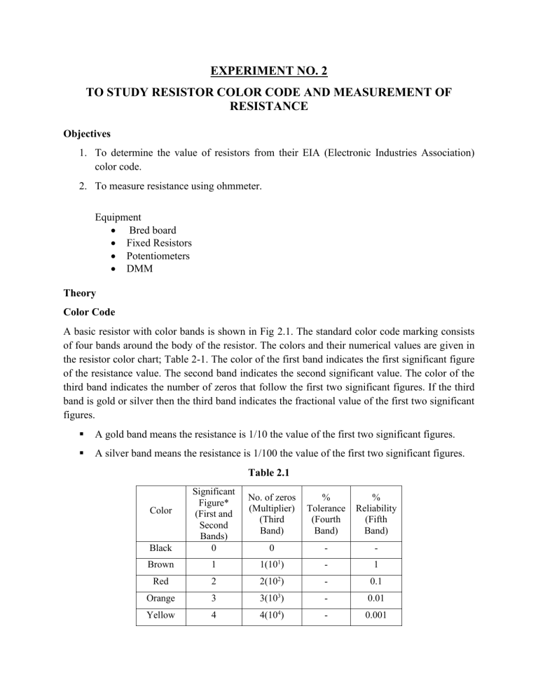
EXPERIMENT NO. 2 TO STUDY RESISTOR COLOR CODE AND MEASUREMENT OF RESISTANCE Objectives 1. To determine the value of resistors from their EIA (Electronic Industries Association) color code. 2. To measure resistance using ohmmeter. Equipment • Bred board • Fixed Resistors • Potentiometers • DMM Theory Color Code A basic resistor with color bands is shown in Fig 2.1. The standard color code marking consists of four bands around the body of the resistor. The colors and their numerical values are given in the resistor color chart; Table 2-1. The color of the first band indicates the first significant figure of the resistance value. The second band indicates the second significant value. The color of the third band indicates the number of zeros that follow the first two significant figures. If the third band is gold or silver then the third band indicates the fractional value of the first two significant figures. ▪ A gold band means the resistance is 1/10 the value of the first two significant figures. ▪ A silver band means the resistance is 1/100 the value of the first two significant figures. Table 2.1 Black Significant Figure* (First and Second Bands) 0 Brown 1 1(101) - 1 Red 2 2(102) - 0.1 Orange 3 3(103) - 0.01 Yellow 4 4(104) - 0.001 Color No. of zeros (Multiplier) (Third Band) % Tolerance (Fourth Band) % Reliability (Fifth Band) 0 - - Green 5 5(105) - - Blue 6 6(106) - - Violet 7 7(107) - - Gray 8 8(108) - - 9 White 9 9(10 ) - - Gold - (0.1 or 10-1) 5 - Silver - (0.01 or 102 ) 10 - No color - - 20 - lead lead Percent tolerance Number of zeros (multiplier) second significant figure first significant figure Fig 2.1 The fourth band indicates the percent tolerance of the resistance. Percent tolerance is the amount the resistance may vary from the value indicated by the color code. Because the resistors are mass-produced, variations in materials will affect their resistance. Tolerances are usually given as plus or minus of the nominal, or color-code value. Example: Brown 1 Red Orange Gold 2 1035% = 12 K , ±5% The fifth band is a reliability factor, which gives the percent of failure per one thousand hours of use. For instance, a 1% failure rate would reveal that one out of every 100 would fail to fall within the tolerance range after 1000 hours of use. High precision resistors have five bands. The first three bands indicate the first three significant figures of the resistance; the fourth band indicates the number of zeros; the fifth band is the percent tolerance. Percent tolerance for these resistors ranges from 0.1 percent to 2 percent. Wire wound high wattage resistors usually are not color-coded but have the resistance value and wattage ratting printed on the body of the resistor. Variable Resistors In addition to fixed resistors, variable resistors are used extensively in electronics. Two types of variable resistors are the rheostat and the potentiometer. Potentiometer Volume controls used in radio; contrast and brightness control of television receivers are typical examples of potentiometers. Figure below shows the inside of potentiometer. (a)Actual Shape (b) Inside of potentiometer Fig 2.2 Rheostat This is the simplest way of using a variable resistor. Two terminals are used: one connected to an end of the track, the other to the moveable wiper. Turning the spindle changes the resistance between the two terminals from zero up to the maximum resistance. Rheostats are often used to vary current, for example to control the brightness of a lamp or the rate at which a capacitor charges. (a) Rheostat (b) Rheostat symbol Fig 2.3 Presets These are miniature versions of the standard variable resistor. They are designed to be mounted directly onto the circuit board and adjusted only when the circuit is built. (a)Preset(Open style) (b)Presets(Close style) Fig 2.4 (c)Symbol representation Nonlinear Resistors Resistance values detailed above are of constant value and do not change if the voltage or current flow alters. But there are circuits that require resistors to change value with a change in temperate or light. This function may not be linear, hence the name non-linear resistors. There are several types of nonlinear resistors, which include Thermistors Negative Temperature Co-efficient (NTC) as shown in figure 1.5(a); their resistance lowers with temperature rise. Positive Temperature Co-efficient (PTC) as shown in figure 1.5(b); their resistance increases with the temperature rise. Light Dependant Resistors Light Dependent Resistors (LDR) figure1.5(c); their resistance lowers with the increase in light. Voltage dependent Resistors (VDR); their resistance critically lowers as the voltage exceeds a certain value. Symbols and shapes of some of these nonlinear resistors are shown below. Fig 2.5 Nonlinear resistors – (a) NTC, (b) PTC, (c) LDR Resistors Power Rating The Power absorbed in a resistor is given by 𝑃 = 𝐼² × 𝑅 2.1 𝑃 = 𝑉²/𝑅 2.2 or Where P = Power absorbed in the resistor in watts (W) I = Current through the resistor in amps (A) R = Resistance of the resistor in ohms ( ) V = Voltage across the resistor in volts (V) Resistors of different values are available in different power ratings. The typical power ratings are 1/8W, 1/4W (quarter watt), 1/2W (half watt), 1W, 2W, 5W, and so on. Example 1: A 470 resistor with 20V across it, needs a power rating P = V²/R = 20²/470 = 0.851W. In this case a standard 1W resistor would be suitable Example 2 A 27 resistor with 10V across it, needs a power rating P = V²/R = 10²/27 = 3.7W. A high power resistor with a rating of 5W would be suitable. Thus when selecting a particular resistor for a given application, we should specify both its resistance value in and its power rating. A general rule of thumb is to always select a resistor whose power rating is at least double the amount of power it will be expected to handle. That way, it will be able to dissipate any heat it generates very quickly, and will operate at normal temperatures. Experimental Work Measuring Resistance with Ohmmeter A multimeter when set to Ω can measure the resistance and the meter is called ohmmeter. To measure the resistance between two points, say A and B connect one end of ohmmeter to A and the other to point B. The meter display will indicate the value of resistance between A and B. Equipment & Components Required 1. Digital multimeter (DMM) 2. Resistors, (color coded) Procedure 1. You are given with resistors of various values and tolerances. Examine each one and determine its resistance and tolerance according to its color code. Record the coded resistance value, and tolerance in Table 2.2. 2. Using the coded resistance value as a guide, select an appropriate meter range by rotating the multi-range selector switch to Ohms, and measure the resistance of each of the resistors. Record your reading under “measured value” in Table 2.2. 3. Measure and record the resistance of a short length of hookup wire given to you. R= _____Ω. 4. Select one of the resistors in step 1 and connect the wire given in step 3 across it as shown in Fig 1.6. By connecting the wire across the leads of resistor, the resistance has been shot-circuited. Measure the resistance across the resistor-hookup wire connection. R= _____Ω. Resistor short-circuited by a piece of hookup wire Fig 2.6 Experimental Results Resistors First color band Second color band Third color band Fourth color band % Tolerance Coded value, Measured value, 1 2 3 4 5 Table 2.2 Question: 1. Comment on the behavior of actual resistance measurement and its coded value as indicated by color codes. Explain your answer by referring to the results in Table 2.2. ________________________________________________________________________ ________________________________________________________________________ ________________________________________________________________________ ________________________________________________________________________ 2. What are the colors of the bands for each of the following carbon resistors having coded values & tolerances given in table 2.3? Table 2.3 Resistors Coded value Tolerance % 1 2 3 4 5 1 0.12 0.27 2.2M 820 5 10 5 10 20 DISCUSSION AND CONCLUSION First color band Second color band Third color band Fourth color band Evaluation Chart Total Marks Participation in the Lab 3 Accuracy of Results Obtained 4 Viva 3 Total 10 Obtained Marks Comments from Lab Instructor: _______________________ Date _______________________ Instructor’s Signature


