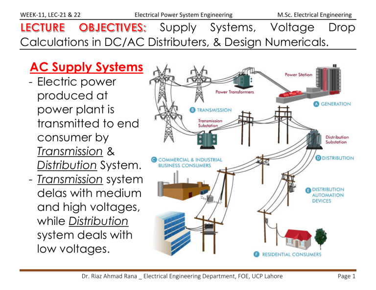
WEEK-11, LEC-21 & 22 Electrical Power System Engineering M.Sc. Electrical Engineering Supply Systems, Voltage Drop Calculations in DC/AC Distributers, & Design Numericals. AC Supply Systems - Electric power produced at power plant is transmitted to end consumer by Transmission & Distribution System. - Transmission system delas with medium and high voltages, while Distribution system deals with low voltages. Dr. Riaz Ahmad Rana _ Electrical Engineering Department, FOE, UCP Lahore Page 1 WEEK-11, LEC-21 & 22 Electrical Power System Engineering AC Voltage Levels M.Sc. Electrical Engineering Generation - 3-phase alternators (Y) - 11 – 13.8 kV - Step up transformers (Y/∆) Primary Transmission - 132 kV, 220 kV, 400 kV, 500 kV, 750 kV - 3-phase, 3-wire system - Steel Towers Secondary Transmission - Receiving stations - Received HV. - Step down transformers - 3-phase, 3-wire system - 33 kV or 22 kV Dr. Riaz Ahmad Rana _ Electrical Engineering Department, FOE, UCP Lahore Page 2 WEEK-11, LEC-21 & 22 Electrical Power System Engineering Primary Distribution - Sub-station involved - Received 22 kV or 33 kV. - Step down transformers - 11 KV, 6.6 KV, 3.3 KV - 3-phase, 3-wire system - To feeders Secondary Distribution (Distributers) - Step down distribution transformers - 11 KV to 400V or 230 V. - 3-phase, 4-wire system - To service mains M.Sc. Electrical Engineering Dr. Riaz Ahmad Rana _ Electrical Engineering Department, FOE, UCP Lahore Page 3 WEEK-11, LEC-21 & 22 Electrical Power System Engineering Typical Distribution System M.Sc. Electrical Engineering a) Distribution substation b) Feeders c) Distribution Transformers d) Distributor conductors e) Service mains conductors Dr. Riaz Ahmad Rana _ Electrical Engineering Department, FOE, UCP Lahore Page 4 WEEK-11, LEC-21 & 22 Electrical Power System Engineering Distribution Substation (Dist. S/S) - Transforms voltage M.Sc. Electrical Engineering from one level to other level. - Located near or inside city/town/village/industrial area. - At Dist. S/S, HV from transmission line is stepped down by a step-down transformer to primary distribution level voltage (11 kV). Dr. Riaz Ahmad Rana _ Electrical Engineering Department, FOE, UCP Lahore Page 5 WEEK-11, LEC-21 & 22 Electrical Power System Engineering Distribution Feeders M.Sc. Electrical Engineering - Feeders are conductors emanating from a substation to supply distribution transformer. - They connect sub-station to area where power is to be distributed. - Feeder forms Primary Distribution System. - Voltage levels of dist. feeder are 11- 33 kV. - Feeders are 3-phase, 3-wire connection system. - Feeder is not directly connected to load. - As no tappings are taken from the feeders so that the current remains same throughout. - Feeder is designed for its current carrying capacity. Dr. Riaz Ahmad Rana _ Electrical Engineering Department, FOE, UCP Lahore Page 6 WEEK-11, LEC-21 & 22 Electrical Power System Engineering Distribution transformer M.Sc. Electrical Engineering - A distribution transformer, is a stepdown 3-phase transformer. - Steps down 11 kV to 400 V. - Line to line voltage is 400 V & Phase voltage is 230 V. - Primary winding is usually delta connected, while secondary side is star connected. - Equipment & system earthing is provided for human and device safety. Dr. Riaz Ahmad Rana _ Electrical Engineering Department, FOE, UCP Lahore Page 7 WEEK-11, LEC-21 & 22 Electrical Power System Engineering Distributors M.Sc. Electrical Engineering - Distributor is a line or conductor which takes the output of distribution transformer and supplies power to consumers. - It is 3-phase, 4-wire connection system. - Voltage levels of distributor are 400 V and 230 V. - Distributor is directly connected to load. - Tappings are taken along the length of a distributor conductor for power supply to the end consumers. - The current through a distributor is not constant as tappings are taken at various places throughout its length. - Voltage drop along the length is the main consideration while designing a distributor conductor. Service Mains - Small cables which connect distributers to consumer DB. Dr. Riaz Ahmad Rana _ Electrical Engineering Department, FOE, UCP Lahore Page 8 WEEK-11, LEC-21 & 22 Electrical Power System Engineering Primary Distribution System M.Sc. Electrical Engineering - It is that part of an AC distribution system which operates at somewhat higher voltages than general residential consumer utilization. - Commonly used primary distribution voltages in most countries are 11 kV, 6.6 kV and 3.3 kV. - Primary distribution handles large consumers such as factories and industries. - Primary distribution is carried out by 3-phase, 3-wire system. Dr. Riaz Ahmad Rana _ Electrical Engineering Department, FOE, UCP Lahore Page 9 WEEK-11, LEC-21 & 22 Electrical Power System Engineering Secondary Distribution System M.Sc. Electrical Engineering - This part directly supplies to the residential end consumers. - Domestic consumers are fed with single phase supply at 230 volts. - Three phase supply may also be provided at 400 volts for big properties, commercial buildings, small factories etc. - Secondary transmission in most countries is carried out by 3-phase, 4-wire system. Dr. Riaz Ahmad Rana _ Electrical Engineering Department, FOE, UCP Lahore Page 10 WEEK-11, LEC-21 & 22 Electrical Power System Engineering Radial Distribution System M.Sc. Electrical Engineering - Radial system has only one power source (substation) for a group of consumers. - Feeders radiate from one substation and feed the distributors at one end. - Power flow is in only one direction. - It is the simplest system and has the lowest initial cost. - Consumers closer to feeder will get maximum voltages, while at far end of feeder, will get low voltages. - As consumers are dependent on single feeder and distributer, any fault on any of these two causes interruption in supply to all consumers. - Radial dist. system is used when when substation is located among the consumers. Dr. Riaz Ahmad Rana _ Electrical Engineering Department, FOE, UCP Lahore Page 11 WEEK-11, LEC-21 & 22 Electrical Power System Engineering M.Sc. Electrical Engineering Parallel Feeders Distribution System - Limitation of radial system is minimized by parallel feeders. - If any feeder gets faulty, other one can provide power. - More reliable than radial feeder. - Load management (load sharing & load shedding) can be done easily. - High initial cost as number of feeders is doubled. - Distribution transformer is fed with common bus-bar. Dr. Riaz Ahmad Rana _ Electrical Engineering Department, FOE, UCP Lahore Page 12 WEEK-11, LEC-21 & 22 Electrical Power System Engineering Ring Main Distribution System M.Sc. Electrical Engineering - Each distribution transformer is fed with two feeders but in different paths. - Feeders form a loop which starts from substation bus-bars, runs through load area feeding distribution transformers and returns to substation bus-bars. - Reliable system similar to parallel feeders’ system. Dr. Riaz Ahmad Rana _ Electrical Engineering Department, FOE, UCP Lahore Page 13 WEEK-11, LEC-21 & 22 Electrical Power System Engineering M.Sc. Electrical Engineering - Feeder covers the whole area of supply in the ring fashion and terminates at the substation from where it was started. - Primaries of distribution transformers form a loop, hence the name given. - Substation supplies to closed Feeder LMNOPQRS. - Distributors are tapped from different points M, O and Q. - If fault occurs at any point “F” of section SLM of Feeder, then section SLM of Feeder can be isolated for repair and supply can be maintained to all consumers via Feeder SRQPONM. Dr. Riaz Ahmad Rana _ Electrical Engineering Department, FOE, UCP Lahore Page 14 WEEK-11, LEC-21 & 22 Electrical Power System Engineering M.Sc. Electrical Engineering Interconnected Distribution System - Feeder ring is energized by two or more than two substations. - Feeder ring ABCD is supplied by S1 and S2 at points D & C respectively. - Distributors are fed at points O, P, Q and R via distribution transformers. - More efficient & reliable system. - Feeders can be fed according to load demand. - Area fed from one substation during peak load hours can be fed from the other generating station or substation for meeting power requirements from increased load. Dr. Riaz Ahmad Rana _ Electrical Engineering Department, FOE, UCP Lahore Page 15 WEEK-11, LEC-21 & 22 Electrical Power System Engineering DC Distribution Calculations M.Sc. Electrical Engineering - Concentrated Loads: Loads that act at a particular point of distributor. For example, domestic loads which are tapped off from a particular point of distributor. - Distributed Loads: Loads which act uniformly at all points of distributor. Ideally, there are no distributed loads. - In dc distribution calculations, point of minimum potential is determined on the distributor. It should not be less than 6% of the rated voltage at consumer’s terminals. - DC distribution calculations for concentrating loads: 1. 2. 3. 4. Distributor fed at one end Distributor fed at both ends Ring Distributor Interconnected distributor Dr. Riaz Ahmad Rana _ Electrical Engineering Department, FOE, UCP Lahore Page 16 WEEK-11, LEC-21 & 22 Electrical Power System Engineering DC Distributor Fed at One End M.Sc. Electrical Engineering AB → dc distributor fed at point “A” having loads I1 tapped at point C, I2 at D, I3 at E and I4 at F. Dr. Riaz Ahmad Rana _ Electrical Engineering Department, FOE, UCP Lahore Page 17 WEEK-11, LEC-21 & 22 Electrical Power System Engineering M.Sc. Electrical Engineering Dr. Riaz Ahmad Rana _ Electrical Engineering Department, FOE, UCP Lahore Page 18 WEEK-11, LEC-21 & 22 Electrical Power System Engineering M.Sc. Electrical Engineering Dr. Riaz Ahmad Rana _ Electrical Engineering Department, FOE, UCP Lahore Page 19 WEEK-11, LEC-21 & 22 Electrical Power System Engineering M.Sc. Electrical Engineering DC Distributor Fed at Both Ends with Equal Voltages - Consider a distributor AB fed at both ends with equal voltages V volts and having concentrated loads I1 , I2 , I3 , I4 and I5 at points C, D, E, F and G respectively. - As we move away from one of the feeding points, say A, p.d. goes on decreasing till it reaches the minimum value at some load point, say E, and then again starts rising and becomes V volts as we reach the other feeding point B. - All currents tapped off between points A and E (minimum p.d. point) will be supplied from feeding point A while those tapped off between B and E will be supplied from feeding point B. Dr. Riaz Ahmad Rana _ Electrical Engineering Department, FOE, UCP Lahore Page 20 WEEK-11, LEC-21 & 22 Electrical Power System Engineering M.Sc. Electrical Engineering - Current tapped off at point E will be partly supplied from A and partly from B. If these currents are x and y respectively, then, I3= x + y - The point at which current comes from both ends of the distributor is called point of minimum potential. - If current supplied by feeding end A is Ia, current distribution in various sections of distributor is given as: Dr. Riaz Ahmad Rana _ Electrical Engineering Department, FOE, UCP Lahore Page 21 WEEK-11, LEC-21 & 22 Electrical Power System Engineering M.Sc. Electrical Engineering Dr. Riaz Ahmad Rana _ Electrical Engineering Department, FOE, UCP Lahore Page 22 WEEK-11, LEC-21 & 22 Electrical Power System Engineering M.Sc. Electrical Engineering Actual distribution of currents in various sections of distributor AB is given as: Dr. Riaz Ahmad Rana _ Electrical Engineering Department, FOE, UCP Lahore Page 23 WEEK-11, LEC-21 & 22 Electrical Power System Engineering M.Sc. Electrical Engineering Currents are coming to point E from both sides. Hence, E is point of min. potential. Distributor fed at both ends with unequal voltages Dr. Riaz Ahmad Rana _ Electrical Engineering Department, FOE, UCP Lahore Page 24 WEEK-11, LEC-21 & 22 Electrical Power System Engineering M.Sc. Electrical Engineering Dr. Riaz Ahmad Rana _ Electrical Engineering Department, FOE, UCP Lahore Page 25 WEEK-11, LEC-21 & 22 Electrical Power System Engineering M.Sc. Electrical Engineering Dr. Riaz Ahmad Rana _ Electrical Engineering Department, FOE, UCP Lahore Page 26 WEEK-11, LEC-21 & 22 Electrical Power System Engineering M.Sc. Electrical Engineering Dr. Riaz Ahmad Rana _ Electrical Engineering Department, FOE, UCP Lahore Page 27 WEEK-11, LEC-21 & 22 Electrical Power System Engineering M.Sc. Electrical Engineering Dr. Riaz Ahmad Rana _ Electrical Engineering Department, FOE, UCP Lahore Page 28 WEEK-11, LEC-21 & 22 Electrical Power System Engineering M.Sc. Electrical Engineering Dr. Riaz Ahmad Rana _ Electrical Engineering Department, FOE, UCP Lahore Page 29 WEEK-11, LEC-21 & 22 Electrical Power System Engineering Ring Distributor with Interconnector M.Sc. Electrical Engineering - If distributor serving area is large, voltage drop will be high. - To reduce voltage drop, different points of distributor are joined by interconnector conductor. - Interconnector is disconnected to find Thevenin voltage (VTH, or Vo) across it. - Thevenin equivalent resistance (RTH, or Ro) of network lines is calculated viewed from interconnector. - Finally, current of interconnector is calculated by using VTH, RTH and resistance of interconnector. 𝑪𝑪𝑪𝑪𝑪𝑪𝑪𝑪𝑪𝑪𝑪𝑪𝑪𝑪 𝒊𝒊𝒊𝒊 𝒊𝒊𝒊𝒊𝒊𝒊𝒊𝒊𝒊𝒊𝒊𝒊𝒊𝒊𝒊𝒊𝒊𝒊𝒊𝒊𝒊𝒊𝒊𝒊𝒊𝒊𝒊𝒊 𝑩𝑩𝑩𝑩 = 𝑬𝑬𝒐𝒐 𝑹𝑹𝒐𝒐 + 𝑹𝑹𝑩𝑩𝑩𝑩 Dr. Riaz Ahmad Rana _ Electrical Engineering Department, FOE, UCP Lahore Page 30 WEEK-11, LEC-21 & 22 Electrical Power System Engineering M.Sc. Electrical Engineering Dr. Riaz Ahmad Rana _ Electrical Engineering Department, FOE, UCP Lahore Page 31 WEEK-11, LEC-21 & 22 Electrical Power System Engineering M.Sc. Electrical Engineering Dr. Riaz Ahmad Rana _ Electrical Engineering Department, FOE, UCP Lahore Page 32 WEEK-11, LEC-21 & 22 Electrical Power System Engineering M.Sc. Electrical Engineering Dr. Riaz Ahmad Rana _ Electrical Engineering Department, FOE, UCP Lahore Page 33 WEEK-11, LEC-21 & 22 Electrical Power System Engineering M.Sc. Electrical Engineering AC Distribution Calculations - Voltage drops in various sections of line are due to R, X and C of line. - Power factor of sending and receiving end of TL is taken into account. Dr. Riaz Ahmad Rana _ Electrical Engineering Department, FOE, UCP Lahore Page 34 WEEK-11, LEC-21 & 22 Electrical Power System Engineering M.Sc. Electrical Engineering Dr. Riaz Ahmad Rana _ Electrical Engineering Department, FOE, UCP Lahore Page 35 WEEK-11, LEC-21 & 22 Electrical Power System Engineering M.Sc. Electrical Engineering Dr. Riaz Ahmad Rana _ Electrical Engineering Department, FOE, UCP Lahore Page 36 WEEK-11, LEC-21 & 22 Electrical Power System Engineering M.Sc. Electrical Engineering Dr. Riaz Ahmad Rana _ Electrical Engineering Department, FOE, UCP Lahore Page 37 WEEK-11, LEC-21 & 22 Electrical Power System Engineering M.Sc. Electrical Engineering Dr. Riaz Ahmad Rana _ Electrical Engineering Department, FOE, UCP Lahore Page 38
