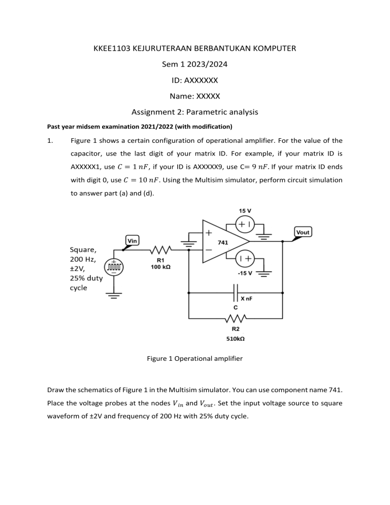
KKEE1103 KEJURUTERAAN BERBANTUKAN KOMPUTER Sem 1 2023/2024 ID: AXXXXXX Name: XXXXX Assignment 2: Parametric analysis Past year midsem examination 2021/2022 (with modification) 1. Figure 1 shows a certain configuration of operational amplifier. For the value of the capacitor, use the last digit of your matrix ID. For example, if your matrix ID is AXXXXX1, use 𝐶 = 1 𝑛𝐹, if your ID is AXXXXX9, use C= 9 𝑛𝐹. If your matrix ID ends with digit 0, use 𝐶 = 10 𝑛𝐹. Using the Multisim simulator, perform circuit simulation to answer part (a) and (d). Figure 1 Operational amplifier Draw the schematics of Figure 1 in the Multisim simulator. You can use component name 741. Place the voltage probes at the nodes 𝑉 𝑖𝑛 and 𝑉𝑜𝑢𝑡 . Set the input voltage source to square waveform of ±2V and frequency of 200 Hz with 25% duty cycle. (a) Perform a suitable analysis to show 6 cycles of waveform for Vin and Vout. Screenshot the schematics with the date and time of Windows taskbar and place it in your Word document. (b) Perform a suitable analysis to plot 6 cycles of waveform that demonstrate the effect of varying the resistor value Rin from 200 kΩ to 400 kΩ with increment of 100kΩ. Display all traces of 𝑉 𝑖𝑛 and 𝑉 𝑜𝑢𝑡 in one graph. (c) Measure the maximum voltage of each trace at the steady state condition. Display the reading of the cursor. Write down these values in your word document. (d) Screenshot the analysis setting window that you have set. (e) Modify the input signal to square wave, ±2V, 200 Hz with 75% duty cycle. Perform a suitable analysis to show 6 cycles of waveform for Vin and Vout. Screenshot the schematics with the date and time of Windows taskbar and place it in your Word document. (f) Modify the input signal to a triangular wave, ±2V and 200 Hz. Perform a suitable analysis to show 6 cycles of waveform for Vin and Vout. Screenshot the schematics with the date and time of Windows taskbar and place it in your Word document.


