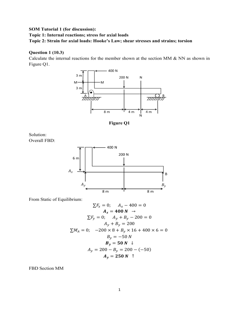
SOM Tutorial 1 (for discussion): Topic 1: Internal reactions; stress for axial loads Topic 2: Strain for axial loads: Hooke’s Law; shear stresses and strains; torsion Question 1 (10.3) Calculate the internal reactions for the member shown at the section MM & NN as shown in Figure Q1. Figure Q1 Solution: Overall FBD: From Static of Equilibrium: ∑𝐹𝑥 = 0; 𝐴𝑥 − 400 = 0 𝑨𝒙 = 𝟒𝟎𝟎 𝑵 → ∑𝐹𝑦 = 0; 𝐴𝑦 + 𝐵𝑦 − 200 = 0 𝐴𝑦 + 𝐵𝑦 = 200 ∑𝑀𝐴 = 0; −200 × 8 + 𝐵𝑦 × 16 + 400 × 6 = 0 𝐵𝑦 = −50 𝑁 𝑩𝒚 = 𝟓𝟎 𝑵 ↓ 𝐴𝑦 = 200 − 𝐵𝑦 = 200 − (−50) 𝑨𝒚 = 𝟐𝟓𝟎 𝑵 ↑ FBD Section MM 1 From Static of Equilibrium: ∑𝐹𝑥 = 0; 𝑉𝑀𝑀 − 400 = 0 𝑽𝑴𝑴 = 𝟒𝟎𝟎 𝑵 → ∑𝐹𝑦 = 0; 𝑭𝑴𝑴 = 𝟎 ∑𝑀𝑀 = 0; 𝑀𝑀𝑀 + 400 × 3 = 0 𝑀𝑀𝑀 = −1200 𝑁 ∙ 𝑚 𝑴𝑴𝑴 = 𝟏𝟐𝟎𝟎 𝑵 ∙ 𝒎 𝑪𝑾 FBD Section NN From Static of Equilibrium: ∑𝐹𝑥 = 0; 𝑭𝑵𝑵 = 𝟎 ∑𝐹𝑦 = 0; 𝑉𝑁𝑁 − 50 = 0 𝑽𝑵𝑵 = 𝟓𝟎 𝑵 ∑𝑀 𝑁 = 0; −𝑀𝑁 − 50 × 4 = 0 𝑀𝑁𝑁 = −200 𝑁 ∙ 𝑚 𝑴𝑵𝑵 = 𝟐𝟎𝟎 𝑵 ∙ 𝒎 𝑪𝑪𝑾 2 Question 2 (7-7) Determine the resultant internal loadings in the beam at cross sections through points D and E. Point E is just to the right of the 15-kN load. Figure Q2 Solution: CORRECTION: Bx = 0 3 Question 3 (7-26) The built-up shaft consists of a pipe AB and solid rod BC. The pipe has an inner diameter of 20 mm and outer diameter of 28 mm. The rod has a diameter of 12 mm. Determine the average normal stress at points D and E and represent the stress on a volume element located at each of these points. Figure Q5 Solution: 4 Question 4. Refer to figure Q4 a. Determine the maximum shearing stress caused by a 4.6-kN ⋅ m torque T in the 76mm-diameter shaft shown. b. Solve part a, if the solid shaft has been replaced by a hollow shaft of the same outer diameter (76-mm) and of 24-mm inner diameter. Figure Q6 Solution: 5 Question 5 (7-74). Refer to figure Q5 The rectangular plate is subjected to the deformation shown by the dashed lines. Determine the average shear strain 𝛾𝑥𝑦 in the plate. Figure Q7. Solution: 6 Question 6 (9-96). Refer to figure Q6 The 50-mm-diameter cylinder is made from Am 1004-T61 magnesium and is placed in the clamp when the temperature is T1 = 20° C. If the 304-stainless-steel carriage bolts of the clamp each have a diameter of 10 mm, and they hold the cylinder snug with negligible force against the rigid jaws. Determine the force in the cylinder when the temperature rises to T2 = 130°C. (𝐸magnesium = 44.7 GPa & 𝐸steel = 193 GPa) Figure Q6. Solution: 7

