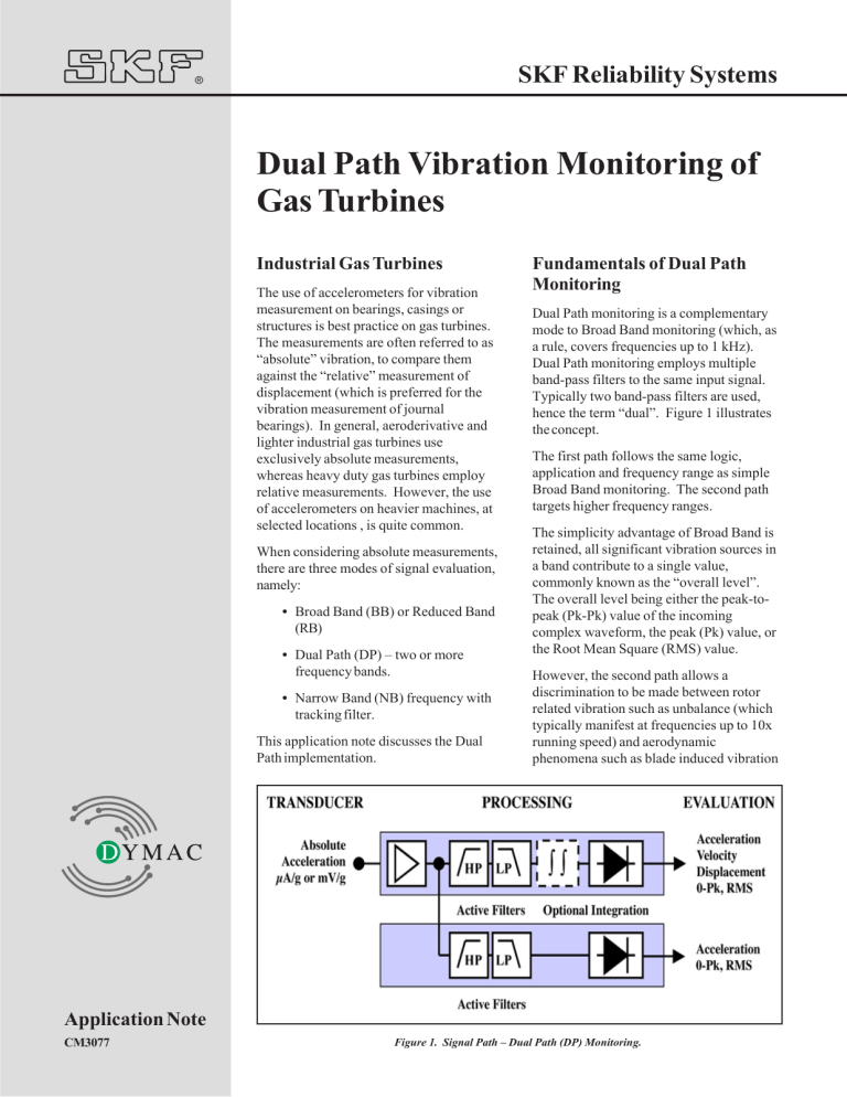
SKF Reliability Systems ® Dual Path Vibration Monitoring of Gas Turbines Industrial Gas Turbines The use of accelerometers for vibration measurement on bearings, casings or structures is best practice on gas turbines. The measurements are often referred to as “absolute” vibration, to compare them against the “relative” measurement of displacement (which is preferred for the vibration measurement of journal bearings). In general, aeroderivative and lighter industrial gas turbines use exclusively absolute measurements, whereas heavy duty gas turbines employ relative measurements. However, the use of accelerometers on heavier machines, at selected locations , is quite common. When considering absolute measurements, there are three modes of signal evaluation, namely: • Broad Band (BB) or Reduced Band (RB) • Dual Path (DP) – two or more frequency bands. • Narrow Band (NB) frequency with tracking filter. This application note discusses the Dual Path implementation. Fundamentals of Dual Path Monitoring Dual Path monitoring is a complementary mode to Broad Band monitoring (which, as a rule, covers frequencies up to 1 kHz). Dual Path monitoring employs multiple band-pass filters to the same input signal. Typically two band-pass filters are used, hence the term “dual”. Figure 1 illustrates the concept. The first path follows the same logic, application and frequency range as simple Broad Band monitoring. The second path targets higher frequency ranges. The simplicity advantage of Broad Band is retained, all significant vibration sources in a band contribute to a single value, commonly known as the “overall level”. The overall level being either the peak-topeak (Pk-Pk) value of the incoming complex waveform, the peak (Pk) value, or the Root Mean Square (RMS) value. However, the second path allows a discrimination to be made between rotor related vibration such as unbalance (which typically manifest at frequencies up to 10x running speed) and aerodynamic phenomena such as blade induced vibration Application Note CM3077 Figure 1. Signal Path – Dual Path (DP) Monitoring. “Dual Path Vibration Monitoring of Gas Turbines” 2 www.skfreliability.com (which occur at much higher frequencies). The Broad Band band pass range of 1,000 Hz typically encompasses rotor vibration. The second path will need to cover frequencies well beyond 1,000 Hz. Transducers, Conditioners and Transmission In Dual Path applications, a single accelerometer is used to provide the raw signal for each band pass filter. The transducer is located on the machine’s structure, following recommendations of the turbine manufacturuer. The choice of transducer, its quality and performance, as well as its location on the machine, are crucial criteria for the efficiency of any vibration monitoring system. The choice of transducer for Dual Path is dictated by three fundamental considerations: • Environment – particularly safe or hazardous area (Ex i) requirements. • Operating Temperatures. • Frequency range. The highest frequency measurable by the second path in Dual Path applications is dictated by the upper frequency limit of the selected accelerometer. This implies a more limited choice of transducer than that of Broad Band monitoring. The Vibro-Meter CE 136 model is recommended for Ex i applications with surface temperatures up to up to 260°C, the attached local electronics being limited to 100°C (or 150°C if a non-Ex i environment). Figure 2. Dual Path Accelerometer Chains. Vibro-Meter CA 201 model is recommended for non-Ex i applications with surface temperatures Manufacturer Type Transducer Conditioner Electronics EGT Tornado CE 136 Alstom (GE) MS5001LA CA 201 Solar Centaur CE 136 Exi Manufacturer Specified System Rolls Royce Avon CE 134 Exi Vibro-Meter MMS Vibro-Meter MMS IPC 704 Vibro-Meter MMS Figure 3. Industrial Gas Turbines Using Broad Band Monitoring. “Dual Path Vibration Monitoring of Gas Turbines” 3 www.skfreliability.com up to up to 260°C, with an IPC-704 charge amplifier mounted in a cooler zone. Other Vibro-Meter CA...series accelerometers may be used with temperatures up to 700°C. The main factors which limit the temperature a transducer can withstand is the location and quality of its signal conditioning electronics. Also, in the case of Dual Path monitoring, it is important that there be as little attenuation as possible of the higher frequency components of the vibration signal. To achieve this, a current modulated signal (µA/ g) is used for transmission of the signal to its associated monitoring electronics. Figure 2 illustrates this, the CE 136 model provides a current modulated output from its attached elecrtonics. The CA 201 model provides a current modulated output from the charge amplifier IPC704. The µA/g output can be transmitted over distances between 1000m to 2000m without significant signal attenuation. All the above factors mean that the choice of acceleration sensor is evaluated in great detail by the gas turbine manufacturer and approved as fit-for-purpose by engine type. Figure 3 shows a table of engine types which employ Dual Path monitoring, with approved sensors. Example Application Figure 4 is a measurement point diagram of a Solar Centaur gas turbine driving a turbo-alternator. Three measuring chains monitor the gas turbine: the first on the compressor section, the second on the turbine section, and the third on the gear section. The transducers are mounted on customized brackets fixed to the connecting flanges of the turbine’s casings. Two measuring trains monitor the generator, the transducers being mounted on the bearing caps. The whole system is five channel monitoring, measuring both Dual Path and Broad Band implementations. The three sensors on the gas turbine employ Dual Path, the two alternator sensors use Broad Band. Although only the gas turbine accelerometers require high temperature and frequency performance, the same sensor is used throughout the chain to simplify maintenance, in this example a VibroMeter CE 136 (Ex i version). The Dual Path evaluation of the processed signal is processed as acceleration, displaying g’s (0-Pk) between 1,000Hz and 10 kHz. The Broad Band evaluation of the processed signal is performed in terms of velocity, displaying mm/sec (RMS) between 10 Hz and 1,000 Hz. Figure 4. Example Application. Processing and Evaluation The evaluation of the sensor signal in a Dual Path application follows the principle of Figure 1. As shown in the example, the evaluation of each signal is normally realized using an RMS velocity parameter over 10 Hz to 1,000 Hz, and a peak acceleration parameter for the higher frequency band of 1,000 Hz to 10 kHz. A monitor system therefore will require two displays per measurement point for Dual Path monitoring. The evaluation takes place in a monitoring system such as the VM600 System illustrated in Figure 2. The VM600 system assigns a single filter per channel, and allows two subsequent processed output paths within that filter. Hence to employ two separate frequency bands from the same sensor, two channels must be employed in parallel. Figure 5 shows the Measurement Channel 1 setup for this example application. The output signal of Measurement Channel 1 (GG-COMP) is routed by programming to the inputs of both Processing Channel 1 and Processing Channel 2, see Figures 6 and 7. Figure 6 shows that Processing Channel 1 is set to a broad band monitoring function with a 10 Hz to 1,000 Hz filter. Its “Processed Output 1” is set to mm/sec RMS, see Figure 8. The “Processed Output 2” is unused. The velocity output would have two alarm set-points defined, ALERT and DANGER. The latter may be used for machine shutdown, in order to protect it from excessive vibration levels. This is done by mapping the velocity DANGER output to a relay contact. The higher frequency band is accommodated by Processing Channel 2 – see Figure 7. Again, a broad band monitoring “Dual Path Vibration Monitoring of Gas Turbines” 4 www.skfreliability.com Figure 5. VM600 Input Programming for Example Dual Path Application. Figure 6. VM600 Processing Programming for First Dual Path Channel Filter. “Dual Path Vibration Monitoring of Gas Turbines” 5 www.skfreliability.com Figure 7. VM600 Processing Programming for Second Dual Path Channel Filter. Figure 8. VM600 Processing Programming for Velocity Output. ® "Dual Path Vibration Monitoring of Gas Turbines" Figure 9. VM600 Processing Programming for Acceleration Output. SKF Reliability Systems 4141 Ruffin Road San Diego, California 92123 USA Telephone: (+1) 858-496-3400 FAX: (+1) 858-496-3531 Web: www.skfreliability.com Although care has been taken to assure the accuracy of the data compiled in this publication, SKF does not assume any liability for errors or omissions. SKF reserves the right to alter any part of this publication without prior notice. • SKF is a registered trademark of SKF USA Inc. • All other trademarks are the property of their respective owners. function is selected, but now with a filter of 1,000 Hz to 10,000 Hz. The Channel 2 “Processed Output 1” is set to g’s Peak – see Figure 9. The “Processed Output 2” is unused. The acceleration processing would be assigned only with an ALERT alarm for fault annunciation and diagnosis purposes. The two alternator channels would be assigned to Broad Band monitoring - see Figures 6 and Figure 8. The VM600 is a multi-channel digital monitoring system, with a single monitor card (the MPC-4) fully programmable for virtually all applications. Each MPC-4 card supports four dynamic channels and two speed channels. Considering the above programming, the VM600 protection hardware required for the example in Figure 4 is two MPC-4 cards: MPC-4 Card Number 1: Channel 1.1 Gas Generator Compressor Velocity Channel 2.1 Gas Generator Compressor Acceleration Channel 3.1 Gas Generator Turbine Velocity Channel 4.1 Gas Generator Turbine Acceleration Channel 5.1 Speed-1 Unused Channel 6.1 Speed-2 Unused MPC-4 Card Number 2: CM3077 (3-03) Copyright © 2003 by SKF Reliability Systems ALL RIGHTS RESERVED Channel 7.1 Gas Generator Gearbox Velocity Channel 8.1 Gas Generator Gearbox Acceleration Channel 9.1 Alternator Inboard Velocity Channel 10.1 Alternator Outboard Velocity Channel 11.1 Speed-1 Unused Channel 12.1 Speed-2 Unused


