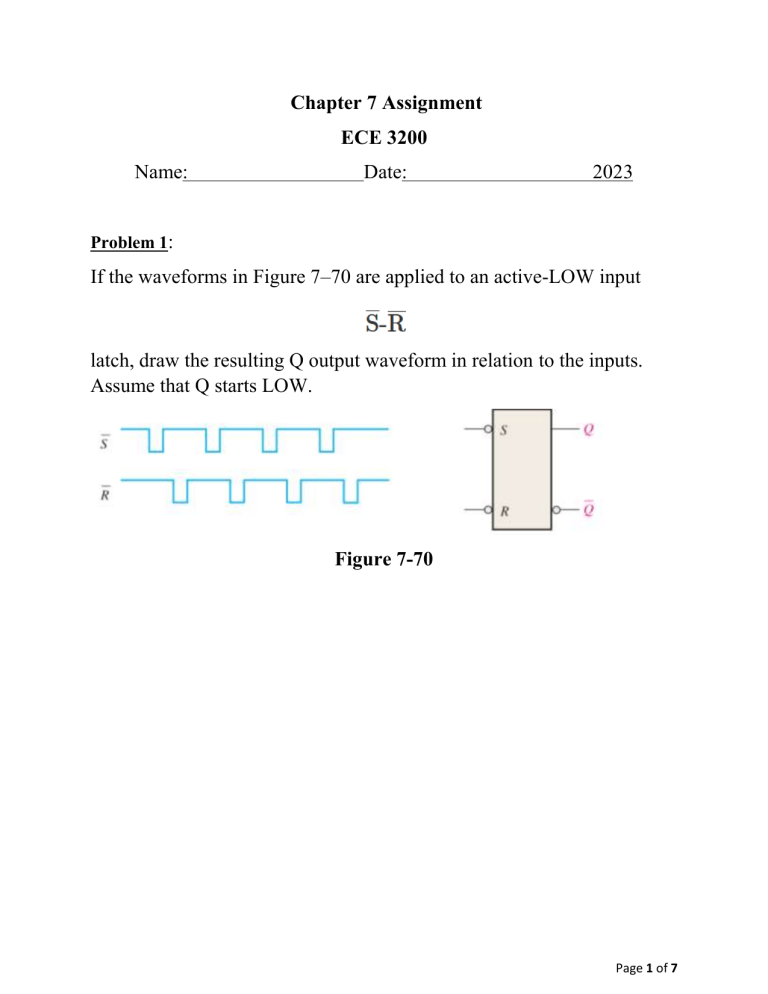
Chapter 7 Assignment ECE 3200 Name: Date: 2023 Problem 1: If the waveforms in Figure 7–70 are applied to an active-LOW input latch, draw the resulting Q output waveform in relation to the inputs. Assume that Q starts LOW. Figure 7-70 Page 1 of 7 Problem 4: For a gated S-R latch, determine the Q and ̅ 𝑄 outputs for the inputs in Figure 7–73. Show them in proper relation to the enable input. Assume that Q starts LOW. Figure 7-73 Page 2 of 7 Problem 8: Two edge-triggered J-K flip-flops are shown in Figure 7–77. If the inputs are as shown, draw the Q output of each flip-flop relative to the clock, and explain the difference between the two. The flip-flops are initially RESET. Figure 7-77 Page 3 of 7 Problem 14: Determine the Q waveform relative to the clock if the signals shown in Figure 7–83 are applied to the inputs of the J-K flip-flop. Assume that Q is initially LOW. Figure 7-83 Page 4 of 7 Problem 17: For the circuit in Figure 7–85, complete the timing diagram in Figure 7– 86 by showing the Q output (which is initially LOW). Assume ̅̅̅̅̅̅ 𝑃𝑅𝐸 and 𝐶𝐿𝑅 remain High. Page 5 of 7 Problem 24: For the circuit in Figure 7–89, determine the maximum frequency of the clock signal for reliable operation if the set-up time for each flip-flop is 2 ns and the propagation delays (tPLH and tPHL) from clock to output are 5 ns for each flip-flop. Figure 7-89 Page 6 of 7 Problem 33: A 74HC00 quad NAND gate IC is used to construct a gated S-R latch on a protoboard in the lab as shown in Figure 7–93. The schematic in part (a) is used to connect the circuit in part (b). When you try to operate the latch, you find that the Q output stays HIGH no matter what the inputs are. Determine the problem. Figure 7-93 Page 7 of 7


