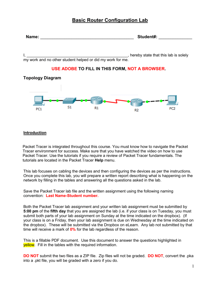
Basic Router Configuration Lab Name: _______________________________________ Student#: ______________ I, ______________________________________________, hereby state that this lab is solely my work and no other student helped or did my work for me. USE ADOBE TO FILL IN THIS FORM, NOT A BROWSER. Topology Diagram Introduction Packet Tracer is integrated throughout this course. You must know how to navigate the Packet Tracer environment for success. Make sure that you have watched the video on how to use Packet Tracer. Use the tutorials if you require a review of Packet Tracer fundamentals. The tutorials are located in the Packet Tracer Help menu. This lab focuses on cabling the devices and then configuring the devices as per the instructions. Once you complete this lab, you will prepare a written report describing what is happening on the network by filling in the tables and answering all the questions asked in the lab. Save the Packet Tracer lab file and the written assignment using the following naming convention: Last Name-Student number. Both the Packet Tracer lab assignment and your written lab assignment must be submitted by 5:00 pm of the fifth day that you are assigned the lab (i.e. if your class is on Tuesday, you must submit both parts of your lab assignment on Sunday at the time indicated on the dropbox). (If your class is on a Friday, then your lab assignment is due on Wednesday at the time indicated on the dropbox). These will be submitted via the Dropbox on eLearn. Any lab not submitted by that time will receive a mark of 0% for the lab regardless of the reason. This is a fillable PDF document. Use this document to answer the questions highlighted in yellow. Fill in the tables with the required information. DO NOT submit the two files as a ZIP file. Zip files will not be graded. DO NOT, convert the .pka into a .pkt file, you will be graded with a zero if you do. 1 Packet Tracer When you open Packet Tracer you will see the following dialog box: Replace Guest with your First name and student number in the space marked Name as well as your email address in the space marked E-Mail. In the Addition Info box copy the following bolded sentence and paste it into the blank area. When pasting into Packet Tracer use the mouse and right click to insert the text. Copy and paste the following: I, name/student #, hereby state that this lab is solely my work and no other student helped or did my work for me. Remember: having someone else do any of your work and then submit it as your own is deemed to be one of the items that falls under the heading of Academic Dishonesty. When it is filled in, the User Profile should look like the example shown below. Click OK and then go to File > Save As and save your file as per the instructions on the first page (Last Name-Student number.). You are now ready to start your lab. 2 Addressing Table Device Interface IP Address Subnet Mask Def. Gateway Fa0/0 192.168.1.33 255.255.255.224 N/A S0/0/0 192.168.1.65 255.255.255.224 N/A Fa0/0 192.168.1.97 255.255.255.224 N/A S0/0/0 192.168.1.94 255.255.255.224 N/A PC1 N/A 192.168.1.62 255.255.255.224 192.168.1.33 PC2 N/A 192.168.1.126 255.255.255.224 192.168.1.97 R1 R2 Learning Objectives Upon completion of this lab, you will be able to: Cable a network according to the Topology Diagram. Erase the startup configuration and reload a router to the default state. Perform basic configuration tasks on a router. Configure and activate Ethernet interfaces. Test and verify configurations. Reflect upon and document the network implementation. Scenario In this lab activity, you will create a network that is similar to the one shown in the Topology Diagram. Begin by cabling the network as shown in the Topology Diagram. You will then perform the initial router configurations required for connectivity. Use the IP addresses that are provided in the Topology Diagram to apply an addressing scheme to the network devices. When the network configuration is complete, examine the routing tables to verify that the network is operating properly. 3 Task 1: Cable the Network. i. Cable your network so it is the same as the one in the Topology Diagram. The output used in this lab is from 1841 routers. Be sure to use the appropriate type of Ethernet cable to connect from host to switch, switch to router, and host to router. Be sure to connect the serial DCE cable to router R1 and the serial DTE cable to router R2. Answer the following questions: ii. What type of cable is used to connect the Ethernet interface on a host PC to the Ethernet interface on a switch? iii. What type of cable is used to connect the Ethernet interface on a switch to the Ethernet interface on a router? iv. What type of cable is used to connect the Ethernet interface on a router to the Ethernet interface on a host PC? Task 2: Erase and Reload the Routers. Step 1: Establish a terminal session to router R1. i. Use PC1. Step 2: Enter privileged EXEC mode. i. What is the command that you used to enter the privileged EXEC mode? Step 3: Clear the configuration. i. What is the command that you used to clear the configuration from NVRAM? 4 Step 4: Reload configuration. i. When the prompt returns, issue the reload command. Answer no if asked to save changes. ii. What would happen if you answered yes to the question, “System configuration has been modified. Save?” Step 5: Repeat Steps 1 through 4 on router R2 to remove any startup configuration file that may be present. Task 3: Perform Basic Configuration of Router R1. Step 1: Establish a Terminal session to router R1. Step 2: Enter privileged EXEC mode. Step 3: Enter global configuration mode. i. What is the command you used to enter the global configuration mode? Step 4: Configure the router name as R1. i. What is the command you used to configure the host name on the router? Step 5: Disable DNS lookup. i. Disable DNS lookup. What is the command you used to accomplish this? ii. Why would you want to disable DNS lookup in a lab environment? 5 iii. What would happen if you disabled DNS lookup in a production environment? Step 6: Configure the EXEC mode password. There are two ways to configure the enable password. You will use the secure method of doing this. i. Using the most secure method, configure the EXEC mode password using class for the password. What is the command you used to accomplish this? ii. Why is it not necessary to use the enable password password command? Step 7: Configure a message-of-the-day banner. i. Configure a message-of-the-day banner. What is the command you used? ii. Use the & as the delimiting character, and type in the message shown below. ******************************** !!!AUTHORIZED ACCESS ONLY!!! ******************************** iii. When does this banner display? iv. Why should every router have a message-of-the-day banner? 6 Step 8: Configure the console password on the router. i. Use cisco as the password. When you are finished, exit from line configuration mode. Type in each line needed to do this. ii. What are the commands that you used to accomplish this task? Step 9: Configure the password for the virtual terminal lines. There are 5 virtual terminal lines. i. Use cisco as the password. When you are finished, exit from line configuration mode. Type in each line needed to do this. ii. What are the commands that you used to accomplish this? Step 10: Configure the FastEthernet0/0 interface. i. Configure the FastEthernet0/0 interface with the IP address 192.168.1.33/27 and bring the interface up. Step 11: Configure the Serial0/0/0 interface. i. Configure the Serial0/0/0 interface with the IP address 192.168.1.65/27. ii. Set the clock rate to 64000 and bring the interface up. iii. Why does the interface go down after you bring it up? 7 Step 12: Return to privileged EXEC mode. i. What is the command that you would to accomplish this? Step 13: Save the R1 configuration. i. What is the full syntax to accomplish this? ii. What is the shortest syntax to accomplish this? Task 4: Perform Basic Configuration of Router R2. Step 1: For R2, repeat Steps 1 through 9 from Task 3. Step 2: Configure the Serial 0/0/0 interface. i. Configure the Serial 0/0/0 interface with the IP address 192.168.1.94/27 and bring the interface up. ii. What did you observe when you brought this interface up? Step 3: Configure the FastEthernet0/0 interface. i. Configure the FastEthernet0/0 interface with the IP address 192.168.1.97/27 and bring this interface up. Step 4: Return to privileged EXEC mode. i. Return to privileged EXEC mode using any method you have learned. Step 5: Save the R2 configuration. i. Save the R2 configuration using any method that you have learned. 8 Task 5: Configure IP Addressing on the Host PCs. Step 1: Configure the host PC1. i. Configure the host PC1 that is attached to R1 with an IP address of 192.168.1.62/27 and a default gateway of 192.168.1.33. Step 2: Configure the host PC2. i. Configure the host PC2 that is attached to R2 with an IP address of 192.168.1.126/27 and a default gateway of 192.168.1.97. Task 6: Verify and Test the Configurations. Step 1: Verify that routing tables have the following routes using the show ip route command. The show ip route command and output will be thoroughly explored in upcoming modules. For now, you are interested in seeing that both R1 and R2 have two routes. Both routes are designated with a C. These are the directly connected networks that were activated when you configured the interfaces on each router. If you do not see two routes for each router as shown in the following output, proceed to Step 2. R1#show ip route Codes: C - connected, S - static, R - RIP, M - mobile, B - BGP D - EIGRP, EX - EIGRP external, O - OSPF, IA - OSPF inter area N1 - OSPF NSSA external type 1, N2 - OSPF NSSA external type 2 E1 - OSPF external type 1, E2 - OSPF external type 2 i - IS-IS, su - IS-IS summary, L1 - IS-IS level-1, L2 - IS-IS level-2 ia - IS-IS inter area, * - candidate default, U - per-user static route o - ODR, P - periodic downloaded static route Gateway of last resort is not set C C 192.168.1.32/27 is directly connected, FastEthernet0/0 192.168.1.64/27 is directly connected, Serial0/0/0 -----------------------R2#show ip route Codes: C - connected, S - static, R - RIP, M - mobile, B - BGP D - EIGRP, EX - EIGRP external, O - OSPF, IA - OSPF inter area N1 - OSPF NSSA external type 1, N2 - OSPF NSSA external type 2 E1 - OSPF external type 1, E2 - OSPF external type 2 i - IS-IS, su - IS-IS summary, L1 - IS-IS level-1, L2 - IS-IS level-2 ia - IS-IS inter area, * - candidate default, U - per-user static route o - ODR, P - periodic downloaded static route Gateway of last resort is not set C C 192.168.1.64/27 is directly connected, Serial0/0/0 192.168.1.96/27 is directly connected, FastEthernet0/0 9 Step 2: Verify interface configurations. Another common problem is router interfaces that are not configured correctly or not activated. i. What is the command that you would use to display all the interfaces with their IP address, their interface status (up/down/admin down) and their line protocol status (up/down)? ii. Fill in the tables below for R1 and R2 using this command. Interface FastEthernet0/0 FastEthernet0/1 Serial0/0/0 Serial0/0/1 VLAN1 Interface FastEthernet0/0 FastEthernet0/1 Serial0/0/0 Serial0/0/1 VLAN1 IP Address IP Address OK? R1 Method Status Protocol OK? R2 Method Status Protocol If both interfaces are up and up, then both routes will be in the routing table. Verify this again by using the show ip route command. Step 3: Test connectivity. Test connectivity by pinging from each host to the default gateway that has been configured for that host. i. From the host attached to R1, is it possible to ping the default gateway? ii. From the host attached to R2, is it possible to ping the default gateway? 10 If the answer is no for any of the above questions, troubleshoot the configurations to find the error using the following systematic process: 1. Check the PCs. i. Are they physically connected to the correct router? (Connection could be through a switch or directly.) ii. Are link lights blinking on all relevant ports? 2. Check the PC configurations. i. Do they match the Topology Diagram? 3. Check the router interfaces using the show ip interface brief command. i. Are the interfaces up and up? If your answer to all three steps is yes, then you should be able to successfully ping the default gateway. Step 4: Test connectivity between router R1 and R2. i. From the router R1, is it possible to ping R2 using the command ping 192.168.1.94? ii. From the router R2, is it possible to ping R1 using the command ping 192.168.1.65? If the answer is no for the questions above, troubleshoot the configurations to find the error using the following systematic process: 1. Check the cabling. i. Are the routers physically connected? ii. Are link lights blinking on all relevant ports? 2. Check the router configurations. i. Do they match the Topology Diagram? ii. Did you configure the clock rate command on the DCE side of the link? 3. Check the router interfaces using the show ip interface brief command. i. Are the interfaces “up” and “up”? If your answer to all three steps is yes, then you should be able to successfully ping from R2 to R1 and from R2 to R3. 11 Task 7: Reflection Step 1: Attempt to ping from the host connected to R1 to the host connected to R2. i. Is this ping successful? Step 2: Attempt to ping from the host connected to R1 to router R2. i. Is this ping successful? Step 3: Attempt to ping from the host connected to R2 to router R1. i. Is this ping successful? ii. What is missing from the network that is preventing communication between these devices? 12 Written Assignment portion of the Basic Router Configuration Lab 1. Input all the information in the tables 2. Answer all the questions in the Tasks/Steps in the lab. Please make note of the following: 1. Grades will be earned for well written justifications and applying knowledge from curriculum in well-reasoned responses. 2. All assignments will be vetted through Anti-plagiarism (Turnitin) software. 3. Neglecting to include a statement of authorship will result in a grade of zero for this assignment. 13 USE THIS PAGE FOR ANY OTHER OBSERVATIONS/COMMENTS THAT YOU WISH TO INCLUDE WITH THIS LAB REPORT.
