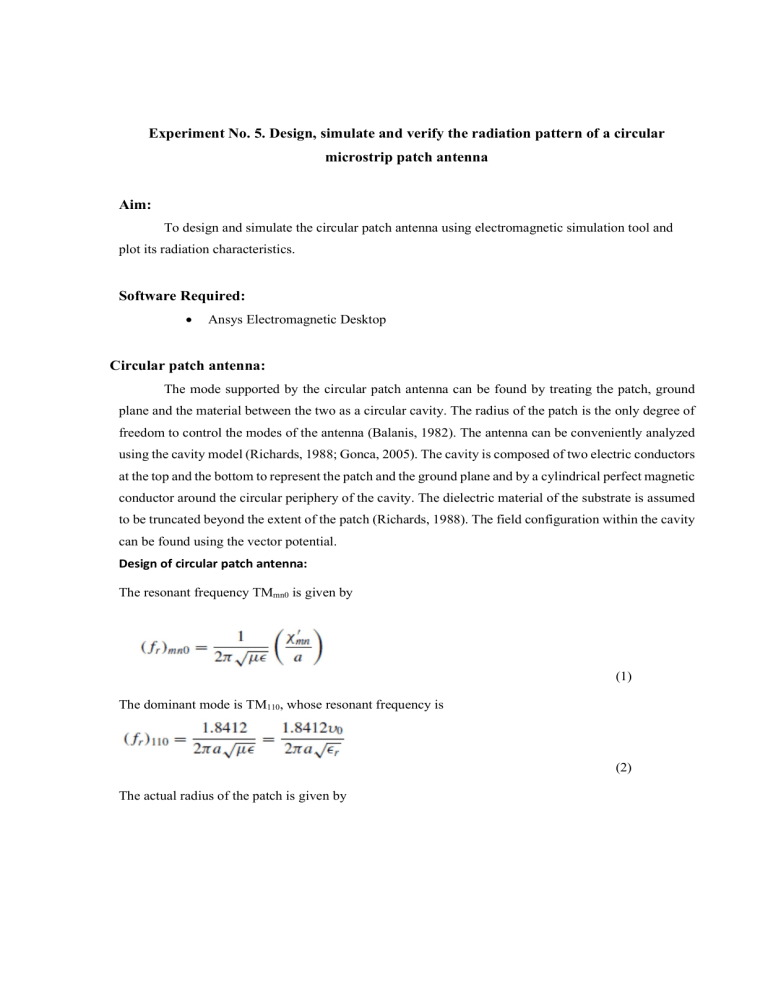
Experiment No. 5. Design, simulate and verify the radiation pattern of a circular microstrip patch antenna Aim: To design and simulate the circular patch antenna using electromagnetic simulation tool and plot its radiation characteristics. Software Required: Ansys Electromagnetic Desktop Circular patch antenna: The mode supported by the circular patch antenna can be found by treating the patch, ground plane and the material between the two as a circular cavity. The radius of the patch is the only degree of freedom to control the modes of the antenna (Balanis, 1982). The antenna can be conveniently analyzed using the cavity model (Richards, 1988; Gonca, 2005). The cavity is composed of two electric conductors at the top and the bottom to represent the patch and the ground plane and by a cylindrical perfect magnetic conductor around the circular periphery of the cavity. The dielectric material of the substrate is assumed to be truncated beyond the extent of the patch (Richards, 1988). The field configuration within the cavity can be found using the vector potential. Design of circular patch antenna: The resonant frequency TMmn0 is given by (1) The dominant mode is TM110, whose resonant frequency is (2) The actual radius of the patch is given by (3) Simulation of an antenna design: Figure 1. Microstrip circular patch antenna Figure 2. Return loss Figure 3. Radiation Pattern Figure 4. 3D gain plot Figure 5. 3D directivity plot Rubrics Split up Conduct of Experiment (15) Observation (15) Record (10) Viva (10) Scale/ Dimension Theoretical Understanding of Antenna trainer kits Verification of connection using suitable cables Marks Awarded (10) (5) Practical Understanding of radiation pattern and working principle of antenna trainer kit (10) Tabulation (5) Presentation (5) Result and Calculation Viva (5) (10) Total Marks Result: Thus the circular patch antenna was designed and simulated using the electromagnetic simulation tool.

