CellAntenna-Radio-Dot-System-Brochure-2020-01-17-1
advertisement

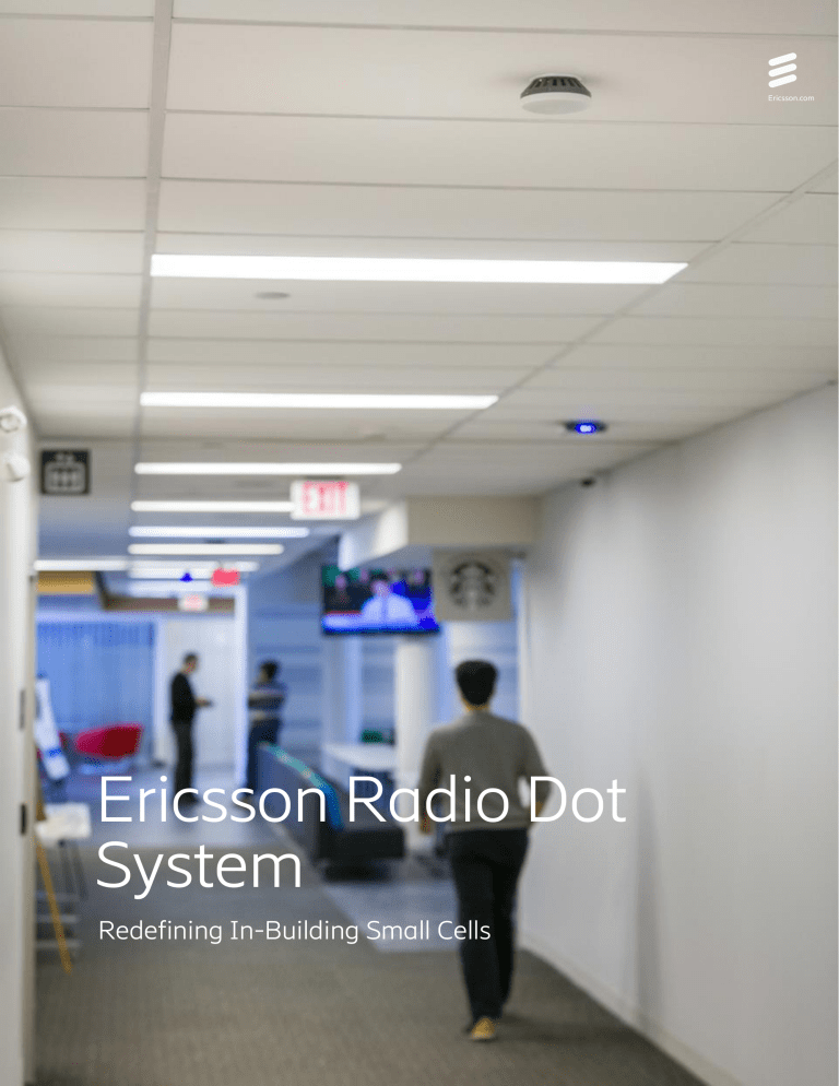
Ericsson.com Ericsson Radio Dot System Redefining In-Building Small Cells As enterprises pursue mobile strategies and consumers depend more heavily on their mobile devices, cellular networks are becoming “mission critical” and superior performance is required. We turn poor coverage into productivity Ericsson Radio Dot System: Superior indoor performance with cost effective deployment and operation for buildings 50,000 square feet and larger. Ericsson Radio Dot System (RDS) provides a flexible, cost-effective architecture and superior network performance ideally suited for medium to large buildings, 50,000 square feet and up. It combines centralized baseband and radio units with visually low-impact antennas. Ericsson innovations enable RF signal, power and control over standard shielded LAN cables for cost-effective deployment with minimal business disruption. Why Radio Dot System? Leading performance with architecture and features resulting in cost-effective deployment and operation. Performance Deployment — Capacity and flexibility – centralized radios provide pooled capacity and design flexibility, dynamically meeting demand wherever it occurs in real time while increasing spectral and hardware efficiency of the system — Seamless mobility – multicast RF transmission optimizes signal quality and eliminates need for handoff zones and interference management while also ensuring the highest hardware and spectral efficiency — Scalability – capacity and coverage for up to 70,000 square feet in a single rack. Single Band Deployment provides enough RF capacity for most buildings — Software features – same software as the macro network enabling 100% feature parity including VoLTE, Carrier Aggregation, 256QAM, Combined Cell, and Lean Carrier — Macro integration – fully integrated into the macro network for optimal performance and KPIs both inside and outside including effective management of strong macro signal scenarios — Spectrum – complete band support including CBRS Band 48 — Installation – use of industrialized IT resources for CAT cable pulling and equipment mounting results in up to 60% reduced cabling cost and up to 70% faster install time compared to DAS — Equipment – small footprint and low power consumption in equipment room with less stringent HVAC requirements. Low visual impact for Radio Dots — Multi-Operator – supports multiple operators and can be deployed in any market. A single dual band Dot can support two operators — Simplicity – no additional gateways or switches required — Cost – extremely competitive total deployment costs including hardware, installation and optimization Operation — Management - OSS and performance management shared with macro network – no new systems to learn or operate — Hardware – no 3rd party elements to impact training, issue resolution procedures and escalation — Evolution – Cost effective and easy to add additional operators and new frequency bands, or add Dots and IRUs for additional coverage. Upcoming 5G NR support in current Dots Radio Dot System Architecture Radio DOT Micro Radio (mRRU) — Indoor optimized ultra compact radio — Discreet and easy to install — Single and dual band versions — Radio and power over LAN cable — Complementing Radio Dot with higher power for large coverage areas such as parking garages — External antenna support, outdoor hardened Indoor Radio Unit (IRU) — Power and control for Radio DOTs — Frequency band independent — FDD/TDD Software defined radio — Remote or co-located with baseband Baseband and RAN Software — RDS + Micro Radio pooled baseband — Backhaul, synchronization and security — WCDMA/LTE SW with feature parity and 3GPP evolution with Ericsson Baseband — Scalable options to meet capacity needs Enclosures — Remote IRU: 1 slot IRU enclosure — RBS 6601: 2 slot enclosure — RBS 6202: 14 slot enclosure Technical specifications Radio Dot System (RDS) Single Band Dot Dual Band Dot Size and weight 3.9” diameter, 10 ounces 5.5” diameter, 16.8 ounces RF power 17 + 17 dBm 2x2 MIMO, Tx/Rx diversity 2x1 MISO, WCDMA common precoding 2 x 17 dBm (per band) 2x2 MIMO, Tx/Rx diversity (per band) 2x1 MISO (per band) Instantaneous Bandwidth (IBW) 40 MHz 80 MHz (40 MHz per band) Omni-directional antenna Built-in Technology WCDMA, LTE FDD, LTE TDD, LTE on CBRS Bands supported Full range of North American WCDMA and LTE bands including CBRS band 48. For additional details contact your Ericsson representative Data speeds LTE: 400/100 Mbps with 2x20 MHz LTE: 400/100 Mbps per band with 2x20 WCDMA: 42/11 Mbps with 4x5 MHz MHz, 256QAM WCDMA: 42/11 Mbps with 4x5 MHz WCDMA carrier Radio Dot Interface Connection between IRU and RD over standard shielded LAN cables for radio signals, control channel and power Cable length to IRU Up to 650 feet Indoor Radio Unit (IRU) Digital Unit (DU) Baseband 31 millimeter Ericsson Radio System form factor Ericsson Radio System baseband Multitude of cabinet options available Baseband options scaling from 3 to 24 IRU support — Frequency band agnostic — Up to 8 Radio Dots per IRU — CPRI connectivity to baseband — Traffic and interference management Feature parity with WDCMA and LTE RAN functionality — VoLTE & HD voice — Carrier aggregation — Regulatory compliance — Combined cell — eMBMS — Soft handover Target Buildings and Design Considerations With RDS, Ericsson provides a superior alternative to Distributed Antenna Systems (DAS), other in-building small cell options, and relying on outside-in macro network coverage. RDS gracefully meets the demands of capacity and performance where others struggle. Because of its superior performance, RDS operates well despite the challenges posed by dense building materials that hinder signal from the outside macro network. RDS can also be combined with the Radio 2203 connected to the same baseband to seamlessly cover indoor and outdoor areas such as parking garages, courtyards, open concourses and parking lots with a single system offering seamless coverage and performance. RDS design methodology is based on dominance margin to achieve overall signal quality. This is preferred over designs based on absolute signal level which can lead to over dimensioning. RDS Solution Components RDS is a complete end-to-end solution including the RF signal source. RDS consists of the Radio Dots, Baseband Units (DU) and Indoor Radio Unit(s) (IRU). The DU and IRU can be connected by fiber or colocated and connected through Digital CPRI cable. The Dot requires a standard CAT6/CAT6A shielded LAN cable for both connectivity and power. This design yields up to 60% reduced cabling cost and up to 70% faster install time compared to DAS, making it more cost-effective for the operator and less disruptive to end customers. Radio Dot: The remotely powered Radio Dot contains the power amplifier and band filter and is the only frequency-dependent component of the complete RDS architecture. New frequencies can be added to the system by adding or swapping Dots. Single and dual band Dots are designed for fast and flexible deployment. The quantity of Dots required is dependent on coverage and performance criteria and will range from 4,000 to 10,000 square feet per Dot. Because each Dot is connected to the same baseband, there is no interference between them, simplifying optimization and ensuring exceptional overall throughput and end user experience. Radio Dot is easy to install Radio Dot Enclosures Supporting multi-band and multi-operator deployments Ericsson offers several enclosures to simplify deployment of multiple frequencies, multiple operators or to deploy the Radio Dot System outdoors. The Radio Dot System is the most flexible small cell solution on the market, with available enclosures that blend seamlessly into any Dual Band Dot can be used for single operator dual band operation or for two operators environment. This provides network operators with customized solutions for their needs and enables a variety of unique deployment opportunities in areas that would be difficult to cover/service with another solution. Hardened Dot for stadium deployments - currently for US market only 24x24 ceiling panel replacement for four Dot concealment Handrail concealment Multi Dot Enclosures Radio Dot offers flexible installation options Indoor Radio Unit (IRU): The IRU 2242 is frequency independent and supports remote software upgrades. It supports and provides power for up to eight Radio Dots, corresponding to an equivalent of 70,000 square feet of floor space coverage in a typical office building. Individual Dots can be connected with up to 650 feet of LAN cable. The IRU can be co-located with the DU in standard Ericsson Radio System cabinets, either an RBS6202 or an RBS6601 When deployed in a distributed architecture, the IRU is housed in a separate 19” sheet metal enclosure with all required mechanicals, fans, cables and alarm which can be mounted in any 19” rack. IRU 2242 Ericsson also offers an AC powered IRU providing even more flexibility. This unit does not require any additional power installation and can be plugged into a standard wall outlet. Digital Unit (DU): The Baseband is the signal source of the Radio Dot System and provides the pooled baseband resources for the building(s) or area. The DU delivers feature parity and roadmap evolution with the macro network and supports key coordination features such as Carrier Aggregation and Combined Cell, vital for multi-antenna indoor deployments. As new features are added to the Ericsson RAN software, they are automatically available in every radio dot system deployment. The Baseband also provides synchronization and transport security functionality, and aggregates the RDS traffic onto a common backhaul connection. Indoor Digital Unit optimized for small deployments – up to 24 (IDU5205) or 48 (IDU2509) Dots Baseband 5216 supports up to 24 IRUs and up to 192 Dots Multiple options for RF signal source or Digital Unit (DU) Multiple options are available to optimize capacity and cost for specific deployments. These range from the cost-effective IDU5205 supporting up to 24 Dots to the large Baseband 5216 that supports up to 192 Dots with multiple options in between. Cabinets: Radio Dot System can be housed in standard Ericsson Radio System cabinets. RBS 6202 RBS 6202 is powered by –48 V DC and supports up to 12 IRU in a single Chassis. RBS 6601 The RBS 6601 is a 2U unit with 2 slots to house IRU and Digital Units and can be mounted in a 19-inch rack. RDS Configuration Options The RDS functional elements can be flexibly connected depending on the design requirements of the application. Medium to large building Subtending nearby RBS Centralized architecture For medium to large buildings, DU and IRU are colocated in same RBS 6202 with star configuration to Radio Dots. CAT6/6a cable is run to individual Dots on each floor. Number of Dots per floor will depend on design criteria. Distributed architecture Large to very large building Campus or large venue For extremely large buildings, multi building campuses and large arenas, a more distributed solution is recommended. In these cases the digital unit is centrally located and the IRUs are distributed. Fiber is used to connect the DU to the IRUs. Buildings can be segmented, with IRU hubs located to serve large sections while minimizing the amount of fiber required. Quantifying Benefits to the Network Full integration ensures peak indoor performance and optimizes the surrounding macro network Surrounding With Radio Dot System Macro only Inside building With Radio Dot System, not only will coverage and throughput be greatly enhanced within the building, but also in the surrounding macro layer. Without RDS, high traffic demand generated indoors consumes a substantial amount of the radio resources of the surrounding outdoor macro cells. Deploying RDS in large high-traffic enterprises offloads the macro layer and serves the indoor users more efficiently. Ericsson performed simulations using a building database and actual site data from a major US city. The network load in the macro layer was increased up to a point where some cells experienced extreme cell overload. Without RDS, performance was poor inside the buildings, and negatively affected in surrounding areas. With RDS deployed in 12 large downtown buildings, both indoor throughput and surrounding areas served by macro cells showed a large improvement in app coverage due to macro offloading. CellAntenna https://cellantenna.com/ 9543409085 Ericsson SE-164 83 Stockholm, Sweden Telephone +46 10 719 0000 www.ericsson.com © Ericsson AB 2018


