The Energv Balance for Chemical Reactors
322
0 3 NA
4 4NA
.44N
A
. f
f
f
N'-' _____o �
______
.J
L
L
'_-'
__
�
�oR
726
738�oR
874n 'R
830 'R
Q
2 x 1 05 BTU/hr
h�
1
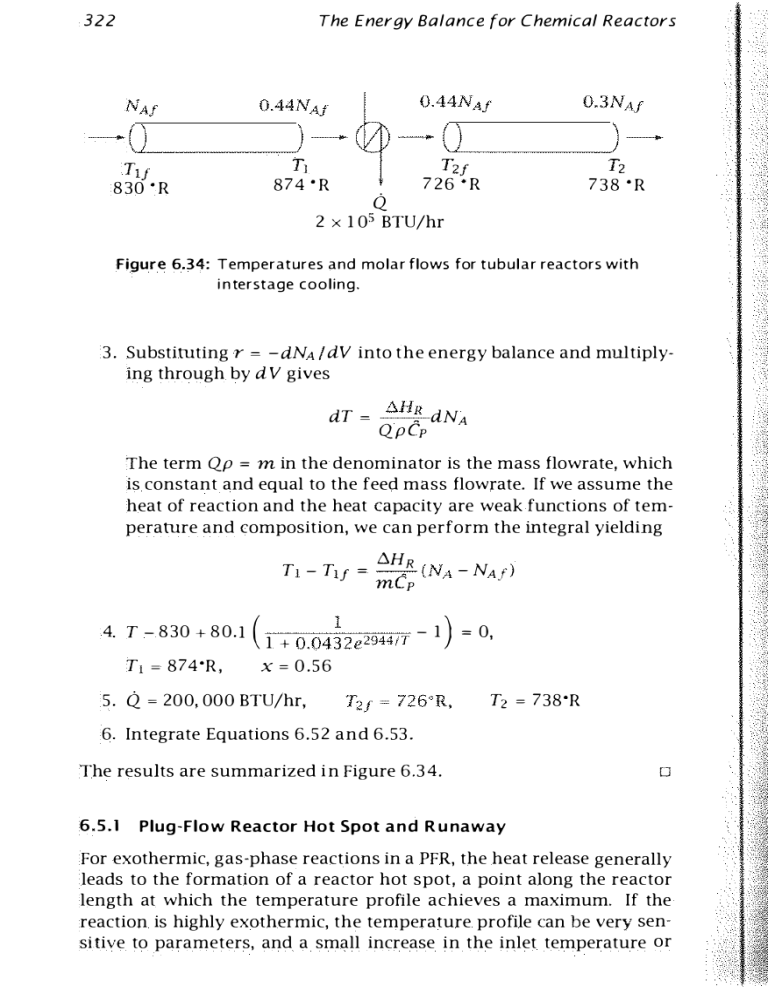
Figure 6.34: Temperatures and molar flows for tubular reactors with
i n terstage cooling.
3.
-dNA ldV into the energy balance and mUltiply­
dV gives
Substituting r =
ing through by
Qp m
dT =
t.H�
Qp Cp
dNA
=
The term
in the denominator is the mass flowrate, which
is constant and equal to the feed mass flowrate. If we assume the
heat of reaction and the heat capacity are weak functions of tem­
perature and composition, we can perform the integral yielding
Tl - Tl
t.HR
-.
- (NA - NAjl
f mep
=
4. T - 830 + 80.1 ( 1 + 0 .04�2 e 2944IT - 1 ) = 0,
Tl = 874'R, x = 0.56
5. Q 200, 000 BTU/hr,
T2 = 738'R
6. Integrate Equations 6.52 and 6.53.
The results are summarized in Figure 6.34.
=
6.5.1
[J
Plug-Flow Reactor Hot Spot a n d R u naway
For exothermic, gas-phase reactions in a PFR, the heat release generally
leads to the formation of a reactor hot spot, a point along the reactor
length at which the temperature profile achieves a maximum. If the
reaction is highly exothermic, the temperature profile can be very sen­
sitive to parameters, and a small increase in the inlet temperature or
6.5 The Plug·Flow Reactor
323
reactant feed concentration, for example, can lead to large changes in
the temperattne profile. sudden, large increase in the reactor temper,
ature due to a small change in feed conditions is known as reactor run·
away. Reactor runaway is highly dangerous, and operating conditions
are normally chosen to keep reactors far from the runaway condition.
The following example, oxidation of o·xylene to phthalic anhydride,
illustrates the PFR hotspot and reactor nmaway.
A
Example 6.5: Oxidation of o-xylene to phthalic anhydride
The gas-phase oxidation of o-xylene to phthalic anhydride
is highly exothermic. The reaction is carried out in PFR tube bundles
with molten salt circulating as the heat transfer fluid [ 10]. The a-xylene
is mixed with air before entering the PFR. The reaction rate is limited
by maintaining a low concentration of hydrocarbon in the feed. The
mole fraction of o-xylene is less than 2%.
Under these conditions, the large excess of oxygen leads to a pseudo­
first-order rate expression
in whlch ex is the a-xylene concentration. The operating pressure is at­
mospheric. Calculate the temperature and o-xylene composition pro­
files. The kinetic parameters are adapted from Van Welsenaere and
Froment and given in Table 6 . 5 [26].
Solution
Ifwe assume constant thermochemical properties, an ideal gas mixture,
and express the mole and energy balances in terms of reactor length,
The Energy Balance for Chemical Reactors
324
Parameter
Value
1922.6
625
625
1.0
1.5
0.0125
0.992
0.373
0.019
1.3636 x 10⁴
- 1 .361 X 1 03
2.6371 x 10⁻³
km
Ta
Tm
Pf
1
tp
R
UO
Yxj
EIR
t:.HR
Qp
Table 6.5:
Units
1
s
K
K
atm
m
m
kJ/kg K
kJ/m2 s K
K
kJjkmol
kg/s
PFR operating conditions and parameters for o·xylene ex·
ample.
we obtain
dNx
dz
=
dT
dz
=
-
A Cr
-f3r + y ( Ta - T)
Nx
RT N
r = k .f..
in which
y=
2rrRUO
•
Qp Cp
and the total molar flow is constant and equal to the feed molar flow
because of the stoichiometry. Figure 6.35 shows the molar flow of 0xylene versus reactor length for several values of the feed temperature.
The corresponding temperature profile is shown in Figure 6.36. We see
a hotspot in the reactor for each feed temperature. Notice the hotspot
temperature increases and moves down the tube as we increase the
feed temperature. Finally, notice if we increase the feed temperature
above ahout 6 3 1 K, the temperature spikes quickly to a large value and
all of the o-xylene is converted by z = 0 . 6 m, which is a classic example
of reactor runaway. To avoid this reactor runaway, we must maintain
the feed temperature below a safe value. This safe value obviously also
depends on how well we can control the composition and temperature
in the feed stream. Tighter control allows us to operate safely at higher
325
6.5 The Plug-Flow Reactor
0.001 6
0.0014
0.0012
'iii'
J
Z
0.001
0.0008
615
0.0006
625
0.0004
6
0.0002
3'71---1--
0
0.2
0
OA
1
0.8
0.6
1 .2
].4
z (m)
Figure
Molar flow of o-xylene versus reactor length for differ­
ent feed temperatures.
6.35:
740
720
700
T(K)
625
680
660
615
640
620
600
0
OA
0.2
0.6
0.8
1
1.2
1A
z (m)
Figure
6.36:
Reactor temperature versus length for different feed
temperatures.
The Energy Balance for Chemical Reactors
326
Ta ( 0 )
=
T(O)
-
-
-
-
Catalyst bed where
reaction occu
rs
Ta W
=
TaJ - - - - - - - - Products
Feed
Pre eate
Reactants
h r
Figure 6.37: Autothermal plug-flow reactor; the heat released by the
exothermic reaction is used to preheat the feed,
feed
temperatures
the producti
on rate.and feed a-xylene mole fractions, which increases
Ianreactor
many applinletictatiemperat
ons, ituires necessary
toghheatreactia feed
ster.eamIf thetoreacti
achieoven
havi
n
g
a
hi
o
n
rat
c, iwentegrathaveiothen. Thepossiessenti
bility taol liodwerea isthtoe reactor
oper­
atialrelsneoased
giscostexotbybyhtermi
heat
use
t
h
e
heat
h
e
react
i
o
n
t
o
heat
the
feed
stream.
As
a
si
m
pl
e
exam­
the gheaturatiionnteigrats known
ion scheme
depiothctedermalin
Fiplplgeuureg·offlot6.hwi3s7reactconcept,
[IJ. oThir. sTheconsi
reactorreactderconfi
as
an
aut
o
r
system
i
s
an
annul
a
r
l
U
be.
The
feed
passes
thel.outTheer regifeedonthenandenters
is heatedthe ithrough
contact
wiotn,h
thewhichoth isthrough
reactor
wal
n
ner
react
i
o
n
regi
fil ed with the catalyst, and flows countercurrently to the feed
0
6.5.2
The Autothermal Plug-Flow Reactor
327
6.5 The Plug-Flow Reactor
stream. The heat released due to reaction in the inner region is used
to heat the feed in the outer region. When the reactor is operating at
steady state, no external heat is required to preheat the feed. Of course,
during the reactor start up, external heat must be supplied to ignite the
reactor.
Although recycle of energy can offer greatly lower operating costs,
the dynamics and contrnl of these reactors may be complex. We next
examine an ammonia synthesis example to show that multiple steady
states are possible. Ammonia synthesis is also interestingbecause of
its large impact on the early development of the chemical engineering
discipline. Quoting Aftalion {2, p. 1 0 1 ]
While physicists and chemists were linking u p t o understand
the structure of matter and giving birth to physical chem­
istry, another discipline was emerging, particularly in the
United States, at the beginning of the twentieth century, that
of chemical engineering
it was undoubtedly the synthesis
of ammonia hy BASF, successfully achieved in 1 9 1 3 in Op­
pau, which forged the linking of chemistry with physics and
engineering as it required knowledge in areas of analysis,
equllibrium reactions, high pressures, catalysis, resistance
of materials. and design of large-scale apparatus.
. . .
Example 6.6: Ammonia synthesis
Calculate the steady-state conversion for the synthesis o f ammonia us­
ing the autothermal process shown in Figure 6.37 [25]. A rate expres­
sion for the reaction
(6.5 4)
over an iron catalyst at 300 atm pressure is suggested by Temkin [ 2 1 ]
r
= LdRT
[
P3 /2
K 2 (1. /N II
P,4
_
PA
pH3! 2
]
(6. 5 5 )
in which PN , PH , PA are the partial pressures o f nitrogen, hydrogen, and
ammonia, respectively, and K is the equilibrium constant for the reac­
tion forming one mole of ammonia. For illustration, we assume the
thermochemical properties are constant and the gases form an ideal­
gas mixture. More accurate thermochemical properties and a more ac­
curate equation of state do not affect the fundameutal behavior pre­
dicted by the reactor model.
The Energy Balance for Chemical Reactors
328
The steady-state material balance for the ammonia is
dNA
= RA = 2 r
dV
NA ( O ) = NAJ
and the other molar flows are calculated from
NN = NNJ - 1/2(NA - NAJ)
NH = NHJ - 3/2 (NA - NAJ)
If we assume an ideal gas in this temperature and pressure range, the
volumetric flowTate is given b y
The energy balance for the reactor i s the usual
Qp Cp
�
dT
= - 6.HR r + q
dV
(6.56)
in which q is the heat transfer laking place between the reacting fluid
and the cold feed
q
= � UO ( Ta - T)
R
The material balances for the feed-heating section are simple be­
cause reaction does not take place without the catalyst. Without reac­
tion, the molar flow of all species are constant and equal to their feed
values and the energy balance for tbe feed-heating section is
�
dTa
= .
dVa -q
Ta (O) TaJ
Q aPa C Pa
(6. 5 7)
=
in which the subscript a represents the fluid in the feed-heating section.
Notice the heat terms are of opposite signs in Equations 6 . 5 7 and 6.56.
If we assume the fluid properties do not change Significantly over the
temperature range of interest, and switch the direction of integration
in Equation 6.57 using dVa = - dV, we obtain
, dTa .
�
Q p Cp
dV q
Ta ( VR ) TaJ
�
(6.58)
(6.59)
6.5
329
The Plug-Flow Reactor
Parameter
Value
e----- p
Units
atm
:lOO
Qo
Ac
l
Tar
y � ---QpCp
f3 LlHR;1'
�
2rrRU"
QpCp
LlC-
0.1 6
1
12
323
rn"/s
0.5
11m
m2
m
K
-2.342
- 1 .2 x 104
7.794 x 101 1
k_lO
2 x 10⁴
E_1/R
-
"
cal/mol
4250
LlW
m2 s K/mol
cal/mol
K
Table 6.6: Parameter values for Example 6.6; heat of reaction and
mixture heat capacity assumed constant.
700 r---,----,--r---,--,
600
500
400
T(K)
300
A
c
B
200
1 00
300
400
500
600
700
800
900
Ta ( O ) (K)
Figure
6.38:
Coolant temperature at reactor outlet versus temper­
ature at reactor inlet, To. (l) versus Ta ( 0 ) ; intersec­
tion with coolant feed tem perature T/-lf i n dicates three
steady-state solutions (A,S,C).
1000
The Energy Balance for Chemical Reactors
330
1000
900
800
T(K)
T
C
700
Ta
600
B
-- __
sao
--
Ta
400
300 L-----L-----�--�--�
a
8
10
6
2
4
12
A T, Ta
z (m)
Figure 6.39: Reactor and coolant temperature profiles versus reac­
tor length; lower (Al, unstable middle (B), and upper (Cl
steady states.
0.2 5 ,.----,----...,.---,.----,----.
....----,
0.2
0.! 5
c
a.!
B
0.05
- - - - - - - - - - - - - - - - - - ­
----- -�
A
2
Figure
6.40:
4
6
z (m)
8
10
Ammonia mole fraction versus reactor length; lower (A),
unstable m i d d le (B), and upper eCl steady states.
12
jj/
6.6 Summary and Notation
Finally we require a boundary condition for the reactor energy balance,
which we have from the fact that the heating fluid enters the reactor
at z = 0, T ( O)
=
Ta (O)· Combining these balances and boundary con­
ditions and converting to reactor length in place of volume gives the
model
dNA 2
AC r
dz
dT
= -fJr + y ( Ta - T)
dz
dT"
y ( T" - T)
dz
=
NA ( O )
T ( O)
=
=
NAJ
Ta (O) -
'
(6.60)
=
in which
Equation 6.60 is a boundary-value problem, rather than an initial-value
problem, because Ta is specified at the exit of the reactor. A simple
solution strategy is to guess the reactor iniet temperature, solve the
model to the exit of tbe reactor, and then compare the computed feed
preheat temperature to the specified value TaJ. This strategy is known
as a shooting method. We guess the missing values required to pro­
duce an initial-value problem. We solve the initial-value problem, and
then iterate on the guessed values until we match the specified bound­
ary conditions. We will see more about boundary-value problems and
shooting methods when we treat diffusion in Chapter 7.
SolUtion
Figure 6.38 shows the results for the parameter values listed in Ta­
ble 6.6, which are based on those used by van Heerden [ 2 5 ] . For given
values of Ta (O), we solve the initial-value problem, Equation 6.60, and
plot the resulting Ta (VR) as the solid line in Figure 6.38. The inter­
section of that line with the feed temperature TaJ
3 2 3 K indicates a
steady-state solution. Notice three steady-state solutions are indicated
in Figure 6.38 for these values of parameters. The profiles in the reac­
tor for these three steady states are shown in Figures 6.39 and 6.40. It
=
is lmportant to operate at the upper steady state so that a reasonably
0
large production of ammonia is achieved.
332
The Energy Balance for Chemical Reactors
Neglect kinetic and potential energies
dt � Q + W; + Wb
dU
.
.
.
(6.6 1 )
Neglect shaft work
(6.62)
(6.63)
Single phase
(6.64)
(6.65)
a. Incompressihle-fluid or constant-pressure reactor
(6.66)
h. Constant-volume reactor
h.l Constant-volume reactor, ideal gas
(6.68)
Table
6.6
6.7:
Energy balances for the batch reactor.
Sum mary
Tables 6.7-6.10 summarize the important energy balances for the batch,
continuous-stirred-tank, semi-batch, and plug-flow reactors. In con­
trast to the material balance, which is reasonably straightforward, choos­
ing the proper energy balance requires some care. It is unwise to se­
lect an energy balance from a book without carefully considering the
assumptions that have been made in the derivation of that particular


