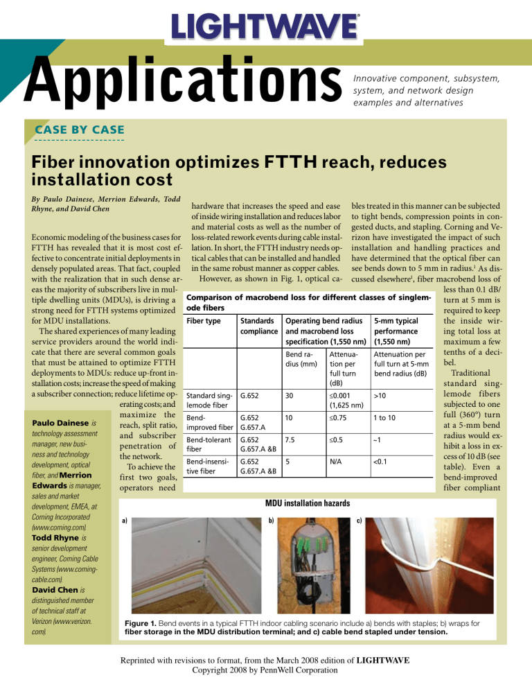
Applications Innovative component, subsystem, system, and network design examples and alternatives case by case Fiber innovation optimizes FTTH reach, reduces installation cost By Paulo Dainese, Merrion Edwards, Todd Rhyne, and David Chen hardware that increases the speed and ease bles treated in this manner can be subjected of inside wiring installation and reduces labor to tight bends, compression points in conand material costs as well as the number of gested ducts, and stapling. Corning and VeEconomic modeling of the business cases for loss-related rework events during cable instal- rizon have investigated the impact of such FTTH has revealed that it is most cost ef- lation. In short, the FTTH industry needs op- installation and handling practices and fective to concentrate initial deployments in tical cables that can be installed and handled have determined that the optical fiber can densely populated areas. That fact, coupled in the same robust manner as copper cables. see bends down to 5 mm in radius.1 As disHowever, as shown in Fig. 1, optical ca- cussed elsewhere1, fiber macrobend loss of with the realization that in such dense areas the majority of subscribers live in mulless than 0.1 dB/ tiple dwelling units (MDUs), is driving a Comparison of macrobend loss for different classes of singlem- turn at 5 mm is strong need for FTTH systems optimized ode fibers required to keep for MDU installations. the inside wirFiber type Standards Operating bend radius 5-mm typical The shared experiences of many leading ing total loss at ­performance compliance and macrobend loss service providers around the world indimaximum a few specification (1,550 nm) (1,550 nm) cate that there are several common goals tenths of a deciBend raAttenuaAttenuation per that must be attained to optimize FTTH bel. dius (mm) tion per full turn at 5-mm deployments to MDUs: reduce up-front inTraditional full turn bend radius (dB) (dB) stallation costs; increase the speed of making standard singa subscriber connection; reduce lifetime op- Standard sing- G.652 lemode fibers 30 ≤0.001 >10 erating costs; and lemode fiber subjected to one (1,625 nm) maximize the Bendfull (360°) turn G.652 10 ≤0.75 1 to 10 Paulo Dainese is reach, split ratio, ­improved fiber G.657.A at a 5-mm bend technology assessment and subscriber Bend-tolerant G.652 radius would ex7.5 ≤0.5 ~1 manager, new busipenetration of fiber hibit a loss in exG.657.A &B ness and technology the network. cess of 10 dB (see Bend-insensiG.652 5 N/A <0.1 development, optical To achieve the table). Even a tive fiber G.657.A &B fiber, and Merrion first two goals, bend-improved Edwards is manager, operators need fiber compliant sales and market development, EMEA, at Corning Incorporated (www.corning.com). Todd Rhyne is senior development engineer, Corning Cable Systems (www.corningcable.com). David Chen is distinguished member of technical staff at Verizon (www.verizon. com). MDU installation hazards a) b) c) Figure 1. Bend events in a typical FTTH indoor cabling scenario include a) bends with staples; b) wraps for fiber storage in the MDU distribution terminal; and c) cable bend stapled under tension. 0803LWcaseF1 Reprinted with revisions to format, from the March 2008 edition of LIGHTWAVE Copyright 2008 by PennWell Corporation Applications mode-field diameter, MFD) is a simple design that gives better bend performance compared to standard singlemode fiber. Typically, standard singlemode fiber has an MFD of about 9.2 μm (at 1,310 nm), and reduced MFD fibers have approximately 8.6 Fiber challenges μm. However, one cannot arbitrarily reduce Improving the macrobend performance of an the MFD without compromising compatibiloptical fiber presents an interesting challenge. ity. Certainly, a fiber with even lower MFD, There are several fibers designs or technolsay for example 5 μm, will have enhanced ogies that can significantly reduce the macperformance, but other optical parameters robend loss. However, a significant challenge will significantly change too, such as disperis the backwards compatibility requirements sion, zero-dispersion wavelength, and cutoff imposed by the telecom industry and stanwavelength. They are all connected by physidards, requirements that severely constrain cal laws, and changing one without changing the design space. In other words, the fiber industry must simultaneously solve the mac- others is challenging. Low cutoff wavelength, robend problem and maintain compatibility for example, guarantees singlemode operawith telecom industry requirements. Some tion and avoids modal dispersion or modal Optimizing power budget conventional designs and more sophisti- interference. Splicing such different MFDs would be a Optimizing the use of the available optical cated fiber technologies are illustrated in Fig. challenge too, and one should expect high power budget from the central office to the 3a, together with the expected performance splice loss. ITU G.652 defines a range for living unit has several advantages; the ability given known design constraints. Note that MFD, exactly to avoid incompatibility isthe y-axis is in logarithmic scale, and changto maximize network reach or increase the sues, and that limits the performance iming the bend radius by only a few millimesplit ratio, as two examples, can reduce the provement one can get with this simple ters can change the loss easily by a factor of overall build costs per subscriber and enable design. All other “conventional” designs, 10. Therefore, when comparing different fiber an earlier return on investment. As a conseshown in orange tones, have similar limitatechnologies, one must pay attention to the quence, the available optical power budget is tions; if required to maintain compatibility, specified bend radius. a very valuable commodity. they do not deliver the desired performance Standard singlemode fiber has the highest The specific power budget depends on the discussed earlier. macrobend loss and is shown in the figure technology of choice: BPON, GPON, EPON, Figure 3b compares the different fiber or RF video overlay. For example, RF video as a reference. A small core fiber (or small overlay has a loss budget of 26 dB, while MDU deployment considerations in a GPON the maximum available power Central MDU budget from the central office to the optical office Local network terminal (ONT) is 28 dB. Indepenconvergence point dent of the specific technology, however, no ONT network operator wants to “waste” budget on inside wiring. The use of a truly bendinsensitive fiber helps them optimize their network design. ODF As shown in Fig. 2, in the absence of any ONU significant bend events in the indoor cabling, the attenuation from the central office to MDU subscriber can be attributed to attenuation Link loss (dB) in the cable, the splitters, the splices, and Repair and 28-dB GPON budget the connectors. By careful choice of quality maintenance 25 1.5 dB components to minimize aging losses and 20 After maintenance environmental variability, the lifetime link 15 margin only 0.3-dB Combined outdoor loss can be accurately predicted. In this sim10 margin remains and indoor link ple example, the total budget of 28 dB is al5 loss 26.1 dB ready “used,” with only 0.4 dB remaining. 0 Cable Splitters Splices Connectors Unexpected additional losses due to bend could cause power budget failure or could deplete the repair and maintenance margin, which would significantly increase the risk Figure 2. In the absence of any significant bending of the cable during the installation within the MDU, the total optical link loss can be attributed to the cable, splitters, splices, and of optical power budget failure during the connectors. 0803LWcaseF2 When a suitable plant maintenance and repair margin is accounted for, many network’s lifetime. Furthermore, cabling networks that optimize the reach from the central office or the number of splits to maximize installations in MDUs are more exposed cost efficiency can be challenged in terms of spare power budget margin. to the G.657.A standard would exhibit a loss on the order of several decibels, and a bendtolerant fiber compliant to the most stringent optical fiber bend standard, G.657.B, would still exhibit high loss in the region of 1 dB. Truly bend-insensitive fibers exhibit macrobend loss of less than 0.1 dB per turn at 5-mm radius, therefore meeting the requirement for MDU inside wiring. As an example, experimental results for different MDU scenarios and different fiber types are presented in Reference 1. A bend-insensitive fiber in harsh, copper-like installation conditions with tight corners, tension, and staples showed a very small total loss of less than 0.2 dB. to unwanted public intervention than any other part of the network, which increases the possibility of network outages due to bend events. Applications Trench volume considerations On the top right is a new fiber a) technology based on a controlled Bend loss “nanostructures” ring in the cladding. A commercial bend-insensitive fiber Ring area π(r 2out –r 2in ) that uses this technology recently has become available; it provides a 10-fold improvement over conventional fiber designs while maintainΔn Index ing backwards compatibility with depression Trench = Area × Δn G.652 standards. volume Fundamentally, this technology uses similar physical principles as the specialty PCFs and HAFs but Trench volume without elevating the cable cutoff wavelength. The way light interacts with a “structured” cladding differentiates these technologies from the more conventional dopant-based b) Singlemode cutoff λ (nm) designs. In addition, the nanostructures technology is compatible with the same mass-production OVD Max. cutoff λ for G.652 compliance manufacturing process used for 1,260 conventional fibers, meeting FTTH volume requirements and exhibiting high manufacturing quality. nanoStructures Fiber based on this technology technology fiber Fluorine-doped fibers can be spliced with any splicing machines, requiring minimal changes Trench volume to splicing recipes, and are easily pro(better macrobend performance) cessed for connectorization. Maximum fluorine-doped trench volume Nanostructures fiber is one of the trench Figure 4. a) Increasing the trench “volume” reduces a) Standard SMF Bend loss (dB/turn) at 1,550 nm fibers illustrated in Fig. an optical fiber’s bend loss (improves the macrobend performance), but there is a tradeoff with backwards 3. The bend perfor- 0803LWcaseF4 Reduced MFD 10 compatibility with the G.652 fiber standard. b) For mance of a depressed ITU 1 Depressed clad chemically doped depressed index trench cladding G.6 index cladding trench fiber, as the trench volume is increased to optimize 57 Trench F-doped A 0.1 fiber is linked to bend performance, the fiber quickly reaches the ITU Trench nanoG.6 the “volume” of the point where it exceeds the 1,260-nm cutoff wave0.01 Structures 57 B trench, where the vol- length requirements of the G.652 and G.657 fiber HAF 0.001 ume is a multiple of standards that ensure that the fiber remains singlemPCF oded in the 1,310-nm window. 0.0001 the ring area and the 0 5 7.5 10 12.5 15 17.5 20 Radius (mm) index depression as cutoff wavelength limit as imposed by the shown in Fig. 4a. Simply, one G.652 and G.657 standards and could beb) can think that the low-index come multimoded in the 1,310-nm waveMacrobend performance trench acts as a barrier that length window. traps light in the core when In the case of a structured cladding, the inthe fiber is bent. Increasing dex depression (or trench volume) depends the trench “volume” will in- strongly on wavelength; this does not hapcrease the bend performance, pen with conventional chemical doping. but there is a performance-to- Specifically, the index depression increases compatibility tradeoff, similar with wavelength, supporting macrobending to the “small MFD” example resistance at the more sensitive, long operadiscussed before. Figure 4b il- tional wavelengths, and reducing the impact Backwards compatibility lustrates that in a fiber with at short wavelengths. Figure 3. Fiber designs do exist with functional (<0.1 dB/ a chemical-doped trench, if Also, large negative refractive index turn) 5-mm bend radius capability, but they lack backwards the trench “volume” exceeds changes are achievable with a nanostruccompatibility with existing G.652 fibers and existing field a certain maximum value, the tures technology on a scale that cannot be 0803LWcaseF3 procedures. A new fiber design was required that breaks fiber will exceed the 1,260-nm attained with conventional fluorine doping the tradeoff between bend performance and compatibility. designs and technologies on a performance versus compatibility chart. Standard singlemode fiber is shown as the reference for both compatibility and performance. On the bottom right is the group of “conventional” designs that use chemical dopants to create modified index profiles. Although these designs exhibit, in general, good compatibility, they have limited gain in performance. Fundamentally, the way light interacts with a chemically doped glass is what limits its performance. On the top left region of the chart we have specialty fiber technologies, for example, photonic crystal fibers (PCFs) and holeassisted fibers (HAFs). Figure 3a also shows the expected performance of these technologies. Those designs use air-holes along the fiber length, on the order of a few microns in diameter, to create a structure in the cladding. HAFs and PCFs are functional down to 5-mm bend radii but are not backwards compatible with G.652 fibers or existing field procedures (splicing, connectorization). This drawback, in addition to being incompatible with the large-scale manufacturing processes that are required to deliver fiber volumes suited to mass deployment of FTTH, precludes their widespread use in the FTTH application space. Fiber type comparisons Applications technology. As a consequence, as shown in Fig. 4b, one can have a greater trench volume and thereby attain a much better bend performance while maintaining low cutoff wavelength, retaining complete backwards compatibility with G.652 standard singlemode fibers. This advanced macrobend performance brings significant technical and economic benefits to FTTH installations by enabling optical fiber cables that can be handled and installed like copper, with no requirements the MDU environment, by accelerating for avoidance of bends and staples as is the subscriber connection and reducing the norm for conventional optical fiber cables. probability of failure during the network’s Operators avoid significant amounts of in- lifetime through protection of the power stallation rework that is caused by bend- budget. induced power loss and associated power budget failure. Reference As a result, network operators are seeing 1. D.Z. Chen et al., “Requirements for Bend Insignificantly high potential for bend-insensitive Fibers for Verizon’s FiOS and FTTH sensitive fibers to reduce the first installed Applications,” pres. at NFOEC, paper NTuC2, cost of an FTTH network, in particular in 2008.


