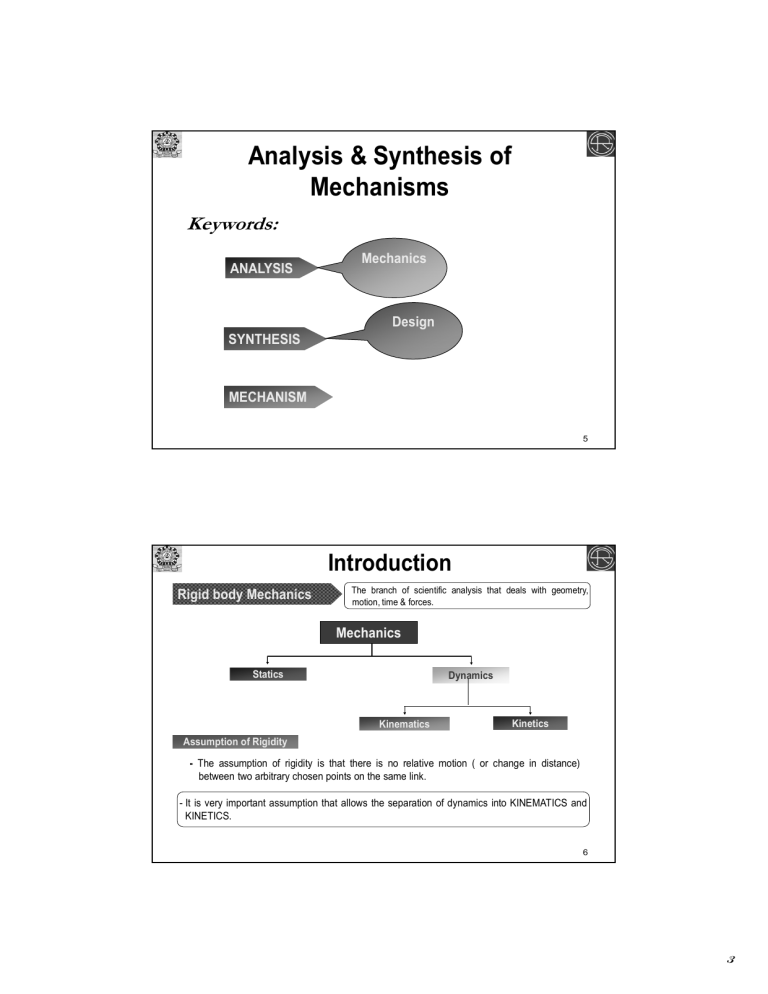
Analysis & Synthesis of Mechanisms Keywords: ANALYSIS Mechanics Design SYNTHESIS MECHANISM 5 Introduction Rigid body Mechanics The branch of scientific analysis that deals with geometry, motion, time & forces. Mechanics Statics Dynamics Kinematics Kinetics Assumption of Rigidity - The assumption of rigidity is that there is no relative motion ( or change in distance) between two arbitrary chosen points on the same link. - It is very important assumption that allows the separation of dynamics into KINEMATICS and KINETICS. 6 3 Manufacture r Stages of Machine Design Custome r Identification of Need Collecting relevant design information & feasibility study Problem statement Task specification or Performance specification Design Conceptualization: Ideation & Innovation Mechanism Synthesis Analysis: Modeling & Simulation Design Optimization & Selection Design Evaluation Detailed Design & Analysis Design Communication & Documentation 7 Prototyping & testing Steps in Machine Design or Robot Design Stress Analysis Machine Design Kinetics Static Kinematics 8 4 Mechanisms: An Introduction Theory of Machine is an Applied science which is used - to understand the relationships between the geometry & motions of the parts of the mechanisms/machines. - To estimate the forces required to produce these motions The study of relative motion between the various parts of a machine & the study of the forces that act on those parts Learning Objectives: Are to provide the engineers the necessary tools to systematically synthesize a system which means scientifically arriving at the best possible configurations & kinematic dimensions of the bodies constituting the system 9 Basics of Mechanism Kinematic Link Kinematic Pair Kinematic Chain One link fixed Mechanism Machine Kinematic Link - Each part of a mechanism which has motion relative to some other part Types of Rigid Links Singular link connected to only one other link Binary link connected to two other links Ternary link connected to three other links Quaternary link connected to four other links 10 5 Kinematics Links Rigid Link It does not undergo any significant deformation while transmitting motion. Flexible Link It is one which is partly deformed in a manner not to affect the transmission of motion . Fluid Link It is deformed by having fluid in a closed vessel & the motion is transmitted through the fluid by pressure. FluidofLink Types Rigid Links Singular link connected to only one other link Binary link connected to two other links Ternary link connected to three other links Quaternary link connected to four other links 11 Basics of Mechanism (contd…) Kinematic Pair - is a joint of two or more links having relative motion between them Classification of Joints or Kinematic pairs According to Nature of Contact Lower Pair Surface or area contact between links Higher Pair Line or point contact between links Sliding/ Prismatic Pair Types of Kinematic Pairs According to Nature of Relative Motion Turning/ Revolute Pair Screw Pair Cylindrical Pair Spherical Pair 12 6 Basics of Mechanism (contd…) Classification of Joints or Kinematic pairs Form closed According to type of physical closure of the joint Forced closed Types of Joints/ Kinematic Pairs The contact is ensured by the geometry or form of the links The contact is ensured by an external load, such as spring load First order joint According to number of links joined (order of joint) Second order joint Higher order joint - Joint order is defined as the number of links joined minus one. First order joint Second order joint Binary joint Ternary joint 13 Basics of Mechanism (contd…) Kinematic Link Kinematic Pair Kinematic Chain One link fixed Mechanism Machine Kinematic Chain - A combination of kinematic pairs joined in such a way the relative motion of any point on a link w.r.t the any other point on other link follows a definite law. Closed Chain Open Chain Mechanism - A kinematic chain in which one link fixed & used for transmitting & transforming motion. 14 7 Mechanism Vs. Machine transfers Mechanism Motion transforms Primary Objectives transfers Machine Energy transforms All Machines are Mechanism but all Mechanisms are not Machine All Machine Tools are Machine but all Machines are not Machine Tool A mechanism is a combination of rigid or restraining bodies so shaped and connected that they move upon each other with a definite relative motion. A machine is a mechanism or a collection of mechanisms which transmits force from the source of power to the resistance to be overcome,and thus perform a mechanical work. 15 Basics of Mechanism (contd…) Mechanism - - assemblage of resistant bodies, connected by joints, to form a kinematic chain with one link fixed & having the purpose of transmitting & transforming motion. provides the definite motion of the parts of a machine. 16 8 Basics of Mechanism (contd…) Mechanism - - Machine assemblage of resistant bodies, connected by joints, to form a kinematic chain with one link fixed & having the purpose of transmitting & transforming motion. provides the definite motion of the parts of a machine. Combination of resisting bodies having definite motions & capable of performing useful work. - Combination of resistant bodies with successfully constrained relative motions which is used to transform, transmit & modify available energy to do some useful work - 17 Basics of Mechanism (contd…) Classification of Mechanism Planar Mechanism Spatial Mechanism All the points of a mechanism move in parallel planes All the points of a mechanism do not move in parallel planes Closed Chain Open Chain Closed Chain Open Chain 18 9 Planar Mechanism 19 Spatial Mechanism 20 10 Basics of Mechanism (contd…) Degrees of Freedom (DOF) - Number of Independent co-ordinates/variables required to completely specify the configuration of the mechanism in motion in space - Minimum number of co-ordinates/variables required to describe a system completely - Minimum number of co-ordinates/variables required to completely specify the relative movement of the links of the mechanism in space Lower Pairs Kinematic Pair Symbol Pair variable DOF Revolute R 1 Prismatic P d 1 Screw or Helical H or d 1 Cylindrical C &d 2 Spherical S , , 3 21 Basics of Mechanism (contd…) Kinematic Pairs in Planar Kinematic Chain Prismatic Pair (P) 1 DOF Revolute Pair (R) Order of joint or joint order 1 DOF First order joint 1 DOF Second order joint 2 DOF (L-1)th order joint (L-1) DOF 22 11 Kinematic Pairs in Planar Kinematic Chain 23 Basics of Mechanism (contd…) Kinematic Diagram - As a result of the assumption of rigidity, many of the intricate details of the actual part shapes are irrelevant when studying the kinematics of a mechanism. - For this reason it is common practice to draw highly simplified schematic diagrams, which contain important features of the shape of each link, such as the relative locations of pair elements, but which completely subdue the real geometry of the manufactured parts. This simplified schematic diagram is known as KINEMATIC DIAGRAM. Such a diagram depicts the essential kinematic features of the mechanism. 24 12 Kinematic Diagram 25 Basics of Mechanism (contd…) Kinematic Diagram 26 13 Basics of Mechanism (contd…) Kinematic Inversion - - Every mechanism has a fixed link called the frame. When different links are chosen as the frame for a given kinematic chain, the relative motions between the various links are not altered, but their absolute motions (those measured w.r.t the frame) may be changed drastically. The process of fixing different links of the same closed kinematic chain to produce different mechanisms is called Kinematic Inversion. Four Inversion of 4 bar linkage 27 Basics of Mechanism (contd…) Kinematic Inversion It is the process of fixing different links of the same closed kinematic chain to produce different mechanisms. 3R1P Mechanism RRRP Mechanism 28 14 Basics of Mechanism (contd…) Kinematic Inversion It is the process of fixing different links of the same closed kinematic chain to produce different mechanisms. 2R2P Mechanism Scotch Yoke RRPP Mechanism Elliptic Trammel 29 Basics of Mechanism (contd…) Equivalent Linkages A mechanism with higher pairs can be replaced by an Equivalent Mechanism with lower pairs. - This equivalence is valid for studying only the instantaneous characteristics. - 30 15 Basics of Mechanism (contd…) Degrees of Freedom (DOF) - Number of Independent co-ordinates/variables required to completely specify the configuration of the mechanism in motion in space - Minimum number of co-ordinates/variables required to describe a system completely - Minimum number of co-ordinates/variables required to completely specify the relative movement of the links of the mechanism in space Lower Pairs Kinematic Pair Symbol Pair variable DOF Revolute R 1 Prismatic P d 1 Screw or Helical H or d 1 Cylindrical C &d 2 Spherical S , , 3 31 32 16 Basics of Mechanism (contd…) Mobility & Degrees of Freedom An arbitrary no. of links connected by a no. of kinematic pairs do not result in a mechanism. Some conditions must be satisfied for a system of interconnected links to serve as a useful mechanism. - The foremost thing which has to be investigated is the mobility of a mechanism in terms of the number of DOF. - Number of Independent co-ordinates/variables required to completely specify the configuration of the mechanism in motion in space For Planar Mechanisms Kutzbach Equation DOF n=number of links F=3(n-1) - 2j j=number of simple hinges or first order joints or equivalent first order joints=(j1+2j2+3j3+…..) ith order joint is equivalent to ‘i’ nos. of first ji is the nos. of ith order joint. order joint or simple hinge Grubler’s Criteria For Planar Mechanisms If F=1, the mechanism is said to be Constrained. 2j - 3n + 4=0 DOF of a mechanism having higher pairs F=3(n-1) - 2j - h h=number of higher pairs 33 Basics of Mechanism (contd…) Equivalent Linkages A mechanism with higher pairs can be replaced by an Equivalent Mechanism with lower pairs. - This equivalence is valid for studying only the instantaneous characteristics. - 34 17 Basics of Mechanism (contd…) Degrees of Freedom Effective DOF of a mechanism having higher pairs & redundant DOF Fe=3(n-1) - 2j – h - Fr Redundant DOF - - If a link can be moved without causing any movement in the rest of the mechanism, then the link is said to be have redundant DOF. Roller 3 can rotate without causing any movement in the rest of the mechanism. - Rod 3 can slide without causing any movement in the rest of the mechanism. 35 Basics of Mechanism (contd…) Degrees of Freedom of Spatial Mechanism F=6(n-1) – 5(R+P+H) - 4C - 3S - Fr R=number of Revolute pair P=number of Prismatic pair H=number of Screw pair C=number of Cylindrical pair S=number of Spherical pair Kinematic Pair in Space Symbol No. of Constraints DOF Revolute R 5 1 Prismatic P 5 1 Screw or Helical H 5 1 Cylindrical C 4 2 Spherical S 3 3 36 18 Basics of Mechanism (contd…) Degrees of Freedom of Planar Mechanism Kinematic Pair in Plane Symbol No. of Constraints DOF Revolute R 2 1 Prismatic P 2 1 Screw or Helical H 2 1 Cylindrical C 1 2 Spherical S 0 3 Degrees of Freedom of Spatial Mechanism Kinematic Pair in Space Symbol No. of Constraints DOF R 5 1 Prismatic P 5 1 Screw or Helical H 5 1 Cylindrical C 4 2 Spherical S 3 3 Revolute 37 Basics of Mechanism (contd…) Degrees of Freedom 38 19 Basics of Mechanism (contd…) Degrees of Freedom 39 Basics of Mechanism (contd…) Grashof’s Law - For a planar four-bar linkage, the sum of the shortest and longest link lengths can not be greater than the sum of the remaining two link lengths if there is to be continuous relative rotation between two members. s=length of the shortest link s+lp+q l=length of the longest link p, q= length of the other two links Grashof Linkage Class-I Kinematic Chain Non-Grashof Linkage Class-II Kinematic Chain Grashof Linkage Class-III Kinematic Chain s+l<p+q s+l>p+q s+l=p+q 20 Basics of Mechanism (contd…) Grashof’s Law - For a planar four-bar linkage, the sum of the shortest and longest link lengths can not be greater than the sum of the remaining two link lengths if there is to be continuous relative rotation between two members. s=length of the shortest link s+lp+q l=length of the longest link p, q= length of the other two links Inversion of Grashof’s linkage Double-crank or drag-link mechanism Crank-rocker mechanism Double-rocker mechanism 41 42 21 43 44 22 45 46 23 Basics of Mechanism (contd…) Index of Merit There are some parameters of the mechanisms, proposed by various researchers, that tell us whether a mechanism is good one or poor one. - Such indices of merit are Mechanical Advantage, Transmission angle etc. - Mechanical Advantage - It is the ratio of the output torque exerted by the driven link (follower) to the necessary input torque required at the driver (crank). Mechanical Advantage= 47 Basics of Mechanism (contd…) Transmission Angle - - - - In practice, besides satisfying kinematic requirements, a mechanism should also move freely. A complete dynamic force analysis is necessary to check this free-running quality. However, even at the stage of kinematic design, we should ensure that the output member receives a large component of the force or torque from the driving member along its direction of movement. we can express the free-running quality of simple mechanisms through an index known as the Transmission Angle. Its optimum value is 90 deg. For a 4R linkage, the Transmission Angle is defined as the acute angle between the coupler and the follower. If ABOB is obtuse, then =-ABOB If ABOB is acute, then =ABOB 48 24 Basics of Mechanism (contd…) Deviation Angle - - Another approach was taken by A. Bock, who suggested working with the directions of the static force and absolute velocity at the point of connection, terming the angle between the directions the deviation angle. Its optimum value is 0 deg. 49 Analysis vs. Synthesis Analysis Input Motions ANALYSIS Output Motions Given Mechanism & its Configuration, dimensions In Kinematic Analysis one is given a mechanism & the task is to determine the various relative motion that can take place in that mechanism. Synthesis decision –making process Innovative or creative process process of creating new mechanism Selecting optimum/best configuration from no. of existing mechanism Determination of optimum dimensions of the elements of the mechanism on the basis of analysis In Kinematic Synthesis one has to be come up with a design of mechanism to generate prescribed motion characteristic. 50 25 Analysis vs. Synthesis Analysis These are the technique that allow the designer to critically examine an already existing design in order to judge its suitability for the task. Analysis is simply a scientific tool Real goal is SYNTHESIS i.e., Design. 51 Computational Tools CAD/CAE software Purpose ADAMS Multi-body dynamic analysis & simulation SimDESIGNER Motion with CATIA Multi-body dynamic analysis & simulation Working Model Multi-body dynamic analysis & simulation 52 26
