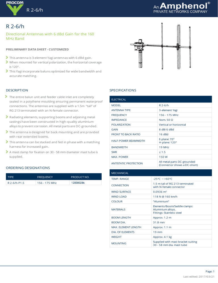
R 2-6/h R 2-6/h Directional Antennas with 6 dBd Gain for the 160 MHz Band PRELIMINARY DATA SHEET - CUSTOMIZED This antenna is 3-element Yagi antennas with 6 dBd gain. When mounted for vertical polarization, the horizontal coverage is 120°. This Yagi incorporate baluns optimized for wide bandwidth and accurate matching. SPECIFICATIONS DESCRIPTION The entire balun unit and feeder cable inlet are completely sealed in a polythene moulding ensuring permanent waterproof ELECTRICAL connections. The antennas are supplied with a 1.5m “tail” of MODEL R 2-6/h RG 213 terminated with an N-female connector. ANTENNA TYPE 3-element Yagi FREQUENCY 156 - 175 MHz IMPEDANCE Nom. 50 Ω POLARIZATION Vertical or horizontal GAIN 8 dBi 6 dBd FRONT TO BACK RATIO 16 dBd This antenna can be stacked and fed in phase with a matching HALF-POWER BEAMWIDTH E-plane: 70° H-plane: 120° harness for increased gain. BANDWIDTH 19 MHz A mast clamp for fixation on 30 - 58 mm diameter mast tube is SWR ≤ 1.5 supplied. MAX. POWER 150 W ANTISTATIC PROTECTION All metal parts DC-grounded (Connector shows a DC-short) Radiating elements, supporting booms and adjoining metal castings have been constructed in high-quality aluminium alloys to prevent corrosion. All metal parts are DC-grounded. The antenna is designed for back mounting and are provided with rear extended booms. ORDERING DESIGNATIONS MECHANICAL TYPE FREQUENCY PRODUCT NO. R 2-6/h-P1.5 156 - 175 MHz 120000286 TEMP. RANGE -25°C Õ +60°C CONNECTION 1.5 m tail of RG 213 terminated with N-female connector WIND SURFACE 0.0936 m² WIND LOAD 118 N @ 160 km/h COLOUR “Aluminium” MATERIALS Elements/Boom/Saddle clamps: Aluminium alloys. Fittings: Stainless steel BOOM LENGTH Approx. 1.2 m BOOM DIA. 31.8 mm MAX. ELEMENT LENGTH Approx. 1.1 m DIA. OF ELEMENTS 19 mm WEIGHT Approx. 4.1 kg MOUNTING Supplied with mast bracket suiting 30 - 58 mm dia. mast tube Page: 1 Last edited: 2017/03/21 R 2-6/h TYPICAL RADIATION PATTERN (E-PLANE) If the antennas are mounted for vertical polarization, these curves show the radiation patterns in the vertical plane. TYPICAL RADIATION PATTERN (H-PLANE) If the antennas are mounted for vertical polarization, these curves show the radiation patterns in the horizontal plane (horizontal coverage). PROCOM A/S reserves the right to amend specifications without prior notice Page: 2 Last edited: 2017/03/21


