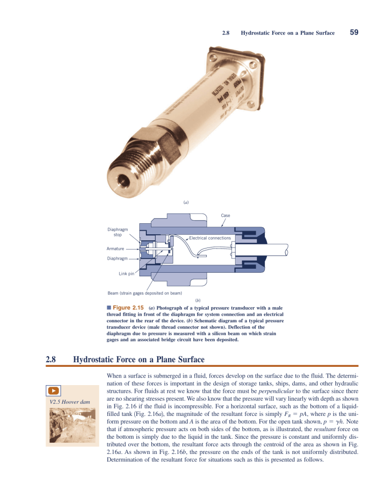
2.8 Hydrostatic Force on a Plane Surface 59 (a) Case Diaphragm stop Electrical connections Armature Diaphragm Link pin Beam (strain gages deposited on beam) (b) ■ Figure 2.15 (a) Photograph of a typical pressure transducer with a male thread fitting in front of the diaphragm for system connection and an electrical connector in the rear of the device. (b) Schematic diagram of a typical pressure transducer device (male thread connector not shown). Deflection of the diaphragm due to pressure is measured with a silicon beam on which strain gages and an associated bridge circuit have been deposited. 2.8 Hydrostatic Force on a Plane Surface V2.5 Hoover dam When a surface is submerged in a fluid, forces develop on the surface due to the fluid. The determination of these forces is important in the design of storage tanks, ships, dams, and other hydraulic structures. For fluids at rest we know that the force must be perpendicular to the surface since there are no shearing stresses present. We also know that the pressure will vary linearly with depth as shown in Fig. 2.16 if the fluid is incompressible. For a horizontal surface, such as the bottom of a liquidfilled tank 1Fig. 2.16a2, the magnitude of the resultant force is simply FR ⫽ pA, where p is the uniform pressure on the bottom and A is the area of the bottom. For the open tank shown, p ⫽ gh. Note that if atmospheric pressure acts on both sides of the bottom, as is illustrated, the resultant force on the bottom is simply due to the liquid in the tank. Since the pressure is constant and uniformly distributed over the bottom, the resultant force acts through the centroid of the area as shown in Fig. 2.16a. As shown in Fig. 2.16b, the pressure on the ends of the tank is not uniformly distributed. Determination of the resultant force for situations such as this is presented as follows. 60 Chapter 2 ■ Fluid Statics Free surface p=0 Free surface p=0 Specific weight = γ h Specific weight = γ p = γh FR p = γh p=0 p=0 (a) Pressure on tank bottom (b) Pressure on tank ends ■ Figure 2.16 (a) Pressure distribution and resultant hydrostatic force on the bottom of an open tank. (b) Pressure distribution on the ends of an open tank. The resultant force of a static fluid on a plane surface is due to the hydrostatic pressure distribution on the surface. For the more general case in which a submerged plane surface is inclined, as is illustrated in Fig. 2.17, the determination of the resultant force acting on the surface is more involved. For the present we will assume that the fluid surface is open to the atmosphere. Let the plane in which the surface lies intersect the free surface at 0 and make an angle u with this surface as in Fig. 2.17. The x–y coordinate system is defined so that 0 is the origin and y ⫽ 0 (i.e., the x axis) is directed along the surface as shown. The area can have an arbitrary shape as shown. We wish to determine the direction, location, and magnitude of the resultant force acting on one side of this area due to the liquid in contact with the area. At any given depth, h, the force acting on dA 1the differential area of Fig. 2.172 is dF ⫽ gh dA and is perpendicular to the surface. Thus, the magnitude of the resultant force can be found by summing these differential forces over the entire surface. In equation form FR ⫽ 冮 gh dA ⫽ 冮 gy sin u dA A A Free surface 0 θ h y hc yc yR dF FR x x A c y xc xR CP dA Centroid, c Location of resultant force (center of pressure, CP) ■ Figure 2.17 Notation for hydrostatic force on an inclined plane surface of arbitrary shape. 2.8 Hydrostatic Force on a Plane Surface 61 where h ⫽ y sin u. For constant g and u FR ⫽ g sin u 冮 y dA (2.17) A The integral appearing in Eq. 2.17 is the first moment of the area with respect to the x axis, so we can write 冮 y dA ⫽ y A c A where yc is the y coordinate of the centroid of area A measured from the x axis which passes through 0. Equation 2.17 can thus be written as FR ⫽ gAyc sin u The magnitude of the resultant fluid force is equal to the pressure acting at the centroid of the area multiplied by the total area. γ hc or more simply as FR ⫽ ghc A (2.18) where, as shown by the figure in the margin, hc is the vertical distance from the fluid surface to the centroid of the area. Note that the magnitude of the force is independent of the angle u. As indicated by the figure in the margin, it depends only on the specific weight of the fluid, the total area, and the depth of the centroid of the area below the surface. In effect, Eq. 2.18 indicates that the magnitude of the resultant force is equal to the pressure at the centroid of the area multiplied by the total area. Since all the differential forces that were summed to obtain FR are perpendicular to the surface, the resultant FR must also be perpendicular to the surface. Although our intuition might suggest that the resultant force should pass through the centroid of the area, this is not actually the case. The y coordinate, yR, of the resultant force can be determined by summation of moments around the x axis. That is, the moment of the resultant force must equal the moment of the distributed pressure force, or FRyR ⫽ 冮 y dF ⫽ 冮 g sin u y dA 2 A A and, therefore, since FR ⫽ gAyc sin u FR = γhc A 冮 y dA c 2 A yR ⫽ yc A The integral in the numerator is the second moment of the area (moment of inertia), Ix, with respect to an axis formed by the intersection of the plane containing the surface and the free surface 1x axis2. Thus, we can write Ix yR ⫽ yc A Use can now be made of the parallel axis theorem to express Ix as A Ix ⫽ Ixc ⫹ Ay2c where Ixc is the second moment of the area with respect to an axis passing through its centroid and parallel to the x axis. Thus, yc FR c Ixc yc A yR ⫽ Ixc ⫹ yc yc A (2.19) As shown by Eq. 2.19 and the figure in the margin, the resultant force does not pass through the centroid but for nonhorizontal surfaces is always below it, since IxcⲐyc A 7 0. The x coordinate, xR, for the resultant force can be determined in a similar manner by summing moments about the y axis. Thus, FR xR ⫽ 冮 g sin u xy dA A 62 Chapter 2 ■ Fluid Statics The resultant fluid force does not pass through the centroid of the area. and, therefore, xR ⫽ 冮 xy dA A ⫽ yc A Ixy yc A where Ixy is the product of inertia with respect to the x and y axes. Again, using the parallel axis theorem,1 we can write xR ⫽ Gate c FR FR left right Ixyc yc A ⫹ xc (2.20) where Ixyc is the product of inertia with respect to an orthogonal coordinate system passing through the centroid of the area and formed by a translation of the x–y coordinate system. If the submerged area is symmetrical with respect to an axis passing through the centroid and parallel to either the x or y axis, the resultant force must lie along the line x ⫽ xc, since Ixyc is identically zero in this case. The point through which the resultant force acts is called the center of pressure. It is to be noted from Eqs. 2.19 and 2.20 that as yc increases the center of pressure moves closer to the centroid of the area. Since yc ⫽ hc Ⲑsin u, the distance yc will increase if the depth of submergence, hc, increases, or, for a given depth, the area is rotated so that the angle, u, decreases. Thus, the hydrostatic force on the right-hand side of the gate shown in the margin figure acts closer to the centroid of the gate than the force on the left-hand side. Centroidal coordinates and moments of inertia for some common areas are given in Fig. 2.18. a –– 2 c x a –– 2 y A = ba A = π R2 1 ba3 Ixc = ––– R 12 x c 1 ab3 Iyc = ––– y b –– 2 Ixyc = 0 (a) Rectangle (b) Circle π R2 A = ––––– ab A = ––– d 2 2 Ixc = 0.1098R R 4 x 4R ––– 3π R Iyc = 0.3927R ba3 Ixc = –––-– 36 2 Ixyc = –ba –––– (b – 2d) 4 c y 4 Ixyc = 0 12 b –– 2 π R4 Ixc = Iyc = ––––– 72 a c x y Ixyc = 0 a –– 3 b+d ––––––– 3 b (c) Semicircle (d) Triangle π R2 A = ––––– 4R ––– 3π 4R ––– 3π c 4 Ixc = Iyc = 0.05488R4 x R Ixyc = –0.01647R4 y (e) Quarter circle ■ Figure 2.18 Geometric properties of some common shapes. 1 Recall that the parallel axis theorem for the product of inertia of an area states that the product of inertia with respect to an orthogonal set of axes 1x–y coordinate system2 is equal to the product of inertia with respect to an orthogonal set of axes parallel to the original set and passing through the centroid of the area, plus the product of the area and the x and y coordinates of the centroid of the area. Thus, Ixy ⫽ Ixyc ⫹ Axcyc. 2.8 l u i d s i n The Three Gorges Dam The Three Gorges Dam being constructed on China’s Yangtze River will contain the world’s largest hydroelectric power plant when in full operation. The dam is of the concrete gravity type, having a length of 2309 m with a height of 185 m. The main elements of the project include the dam, two power plants, and navigation facilities consisting of a ship lock and lift. The power plants will contain 26 Francis-type turbines, each with a capacity of 700 megawatts. The spillway section, which is the center section of the dam, is 483 m long with 23 bottom outlets and 22 surface sluice gates. E XAMPLE t h e N e w 63 s The maximum discharge capacity is 102,500 cu m per second. After more than 10 years of construction, the dam gates were finally closed, and on June 10, 2003, the reservoir had been filled to its interim level of 135 m. Due to the large depth of water at the dam and the huge extent of the storage pool, hydrostatic pressure forces have been a major factor considered by engineers. When filled to its normal pool level of 175 m, the total reservoir storage capacity is 39.3 billion cu m. All of the originally planned components of the project (except for the ship lift) were completed in 2008. (See Problem 2.111.) 2.6 Hydrostatic Force on a Plane Circular Surface GIVEN The 4-m-diameter circular gate of Fig. E2.6a is located in the inclined wall of a large reservoir containing water 1g ⫽ 9.80 kNⲐm3 2. The gate is mounted on a shaft along its horizontal diameter, and the water depth is 10 m above the shaft. 0 0 60° x –––10 y 10 m FIND Determine (b) the moment that would have to be applied to the shaft to open the gate. yc = Stop (a) the magnitude and location of the resultant force exerted on the gate by the water and si –––m yR n 60–°–– F Hydrostatic Force on a Plane Surface Shaft FR c A 4m c (b) SOLUTION A (a) To find the magnitude of the force of the water we can apply Eq. 2.18, Oy Center of pressure FR (a) c FR ⫽ ghc A ᐃ and since the vertical distance from the fluid surface to the centroid of the area is 10 m, it follows that FR ⫽ 19.80 ⫻ 103 NⲐm3 2 110 m214p m2 2 ⫽ 1230 ⫻ 103 N ⫽ 1.23 MN Ixyc yc A ⫹ xc yR ⫽ Ixc ⫹ yc yc A For the coordinate system shown, xR ⫽ 0 since the area is symmetrical, and the center of pressure must lie along the diameter A-A. To obtain yR, we have from Fig. 2.18 Ixc ⫽ pR 4 4 and yc is shown in Fig. E2.6b. Thus, 1pⲐ4212 m2 4 10 m ⫹ sin 60° 110 mⲐsin 60°2 14p m2 2 ⫽ 0.0866 m ⫹ 11.55 m ⫽ 11.6 m yR ⫽ (c) ■ Figure E2.6a–c (Ans) To locate the point 1center of pressure2 through which FR acts, we use Eqs. 2.19 and 2.20, xR ⫽ Ox M and the distance 1along the gate2 below the shaft to the center of pressure is yR ⫺ yc ⫽ 0.0866 m (Ans) We can conclude from this analysis that the force on the gate due to the water has a magnitude of 1.23 MN and acts through a point along its diameter A-A at a distance of 0.0866 m 1along the gate2 below the shaft. The force is perpendicular to the gate surface as shown in Fig. E2.6b. COMMENT By repeating the calculations for various values of the depth to the centroid, hc, the results shown in Fig. E2.6d are obtained. Note that as the depth increases, the distance between the center of pressure and the centroid decreases. (b) The moment required to open the gate can be obtained with the aid of the free-body diagram of Fig. E2.6c. In this diagram w 64 Chapter 2 ■ Fluid Statics is the weight of the gate and Ox and Oy are the horizontal and vertical reactions of the shaft on the gate. We can now sum moments about the shaft and, therefore, M ⫽ FR 1 yR ⫺ yc 2 ⫽ 11230 ⫻ 103 N2 10.0866 m2 ⫽ 1.07 ⫻ 105 N # m 0.4 yR – yc, m a Mc ⫽ 0 0.5 0.3 0.2 (10m, 0.0886 m) 0.1 (Ans) 0 0 5 10 15 20 25 30 hc, m ■ Figure E2.6d E XAMPLE 2.7 Hydrostatic Pressure Force on a Plane Triangular Surface GIVEN An aquarium contains seawater 1g ⫽ 64.0 lbⲐft3 2 to a depth of 1 ft as shown in Fig. E2.7a. To repair some damage to one corner of the tank, a triangular section is replaced with a new section as illustrated in Fig. E2.7b. FIND Determine (a) the magnitude of the force of the seawater on this triangular area, and (b) the location of this force. SOLUTION (a) The various distances needed to solve this problem are shown in Fig. E2.7c. Since the surface of interest lies in a vertical plane, yc ⫽ hc ⫽ 0.9 ft, and from Eq. 2.18 the magnitude of the force is FR ⫽ ghc A ⫽ 164.0 lb Ⲑft3 2 10.9 ft2 3 10.3 ft2 2 Ⲑ2 4 ⫽ 2.59 lb (Ans) COMMENT Note that this force is independent of the tank length. The result is the same if the tank is 0.25 ft, 25 ft, or 25 miles long. 0.3 ft 1 ft 0.3 ft 0.9 ft 2.5 ft (b) The y coordinate of the center of pressure 1CP2 is found from Eq. 2.19, yR ⫽ (b) Ixc ⫹ yc yc A x y and from Fig. 2.18 yc 1 ft Median line yR δA 0.2 ft c 0.1 ft c CP 0.1 ft (c) ■ Figure E2.7b–d ■ Figure E2.7a (Photograph courtesy of Tenecor Tanks, Inc.) xR CP 0.15 ft 0.15 ft (d ) 2.9 Ixc ⫽ xR ⫽ so that 0.0081 Ⲑ36 ft4 ⫹ 0.9 ft 10.9 ft210.09Ⲑ2 ft2 2 ⫽ 0.00556 ft ⫹ 0.9 ft ⫽ 0.906 ft yR ⫽ (Ans) Similarly, from Eq. 2.20 Ixyc yc A ⫹ xc and from Fig. 2.18 Ixyc ⫽ 2.9 65 so that 10.3 ft210.3 ft2 3 0.0081 4 ⫽ ft 36 36 xR ⫽ Pressure Prism 10.3 ft210.3 ft2 2 0.0081 4 10.3 ft2 ⫽ ft 72 72 0.0081Ⲑ72 ft4 ⫹ 0 ⫽ 0.00278 ft 10.9 ft210.09Ⲑ2 ft2 2 (Ans) COMMENT Thus, we conclude that the center of pressure is 0.00278 ft to the right of and 0.00556 ft below the centroid of the area. If this point is plotted, we find that it lies on the median line for the area as illustrated in Fig. E2.7d. Since we can think of the total area as consisting of a number of small rectangular strips of area dA 1and the fluid force on each of these small areas acts through its center2, it follows that the resultant of all these parallel forces must lie along the median. Pressure Prism An informative and useful graphical interpretation can be made for the force developed by a fluid acting on a plane rectangular area. Consider the pressure distribution along a vertical wall of a tank of constant width b, which contains a liquid having a specific weight g. Since the pressure must vary linearly with depth, we can represent the variation as is shown in Fig. 2.19a, where the pressure is equal to zero at the upper surface and equal to gh at the bottom. It is apparent from this diagram that the average pressure occurs at the depth hⲐ2 and, therefore, the resultant force acting on the rectangular area A ⫽ bh is h FR ⫽ pav A ⫽ g a b A 2 which is the same result as obtained from Eq. 2.18. The pressure distribution shown in Fig. 2.19a applies across the vertical surface, so we can draw the three-dimensional representation of the pressure distribution as shown in Fig. 2.19b. The base of this “volume” in pressure-area space is the plane surface of interest, and its altitude at each point is the pressure. This volume is called the pressure prism, and it is clear that the magnitude of the resultant force acting on the rectangular surface is equal to the volume of the pressure prism. Thus, for the prism of Fig. 2.19b the fluid force is The magnitude of the resultant fluid force is equal to the volume of the pressure prism and passes through its centroid. FR ⫽ volume ⫽ 1 h 1gh21bh2 ⫽ g a b A 2 2 where bh is the area of the rectangular surface, A. The resultant force must pass through the centroid of the pressure prism. For the volume under consideration the centroid is located along the vertical axis of symmetry of the surface and at a distance of hⲐ3 above the base 1since the centroid of a triangle is located at h Ⲑ3 above its base2. This result can readily be shown to be consistent with that obtained from Eqs. 2.19 and 2.20. h p h CP h– 3 FR h– 3 FR b γh ( a) γh (b) ■ Figure 2.19 Pressure prism for vertical rectangular area. 66 Chapter 2 ■ Fluid Statics γ h1 h1 B A y1 h2 F1 yA y2 FR p F2 C D E γ (h2 - h1) (a) (b) ■ Figure 2.20 Graphical representation of hydrostatic forces on a vertical rectangular surface. This same graphical approach can be used for plane rectangular surfaces that do not extend up to the fluid surface, as illustrated in Fig. 2.20a. In this instance, the cross section of the pressure prism is trapezoidal. However, the resultant force is still equal in magnitude to the volume of the pressure prism, and it passes through the centroid of the volume. Specific values can be obtained by decomposing the pressure prism into two parts, ABDE and BCD, as shown in Fig. 2.20b. Thus, FR ⫽ F1 ⫹ F2 where the components can readily be determined by inspection for rectangular surfaces. The location of FR can be determined by summing moments about some convenient axis, such as one passing through A. In this instance FRyA ⫽ F1y1 ⫹ F2 y2 The use of the pressure prism concept to determine the force on a submerged area is best suited for plane rectangular surfaces. and y1 and y2 can be determined by inspection. For inclined plane rectangular surfaces the pressure prism can still be developed, and the cross section of the prism will generally be trapezoidal, as is shown in Fig. 2.21. Although it is usually convenient to measure distances along the inclined surface, the pressures developed depend on the vertical distances as illustrated. The use of pressure prisms for determining the force on submerged plane areas is convenient if the area is rectangular so the volume and centroid can be easily determined. However, for other nonrectangular shapes, integration would generally be needed to determine the volume and centroid. In these circumstances it is more convenient to use the equations developed in the previous section, in which the necessary integrations have been made and the results presented in a convenient and compact form that is applicable to submerged plane areas of any shape. The effect of atmospheric pressure on a submerged area has not yet been considered, and we may ask how this pressure will influence the resultant force. If we again consider the pressure distribution on a plane vertical wall, as is shown in Fig. 2.22a, the pressure varies from zero at the surface to gh at the bottom. Since we are setting the surface pressure equal to zero, we are using γ h1 h1 h2 γ h2 ■ Figure 2.21 Pressure variation along an inclined plane area. 2.9 patm patm h p FR Pressure Prism 67 patm patm A patm A FR γh (a) (b) ■ Figure 2.22 Effect of atmospheric pressure on the resultant force acting on a plane vertical wall. The resultant fluid force acting on a submerged area is affected by the pressure at the free surface. E XAMPLE atmospheric pressure as our datum, and thus the pressure used in the determination of the fluid force is gage pressure. If we wish to include atmospheric pressure, the pressure distribution will be as is shown in Fig. 2.22b. We note that in this case the force on one side of the wall now consists of FR as a result of the hydrostatic pressure distribution, plus the contribution of the atmospheric pressure, patm A, where A is the area of the surface. However, if we are going to include the effect of atmospheric pressure on one side of the wall, we must realize that this same pressure acts on the outside surface 1assuming it is exposed to the atmosphere2, so that an equal and opposite force will be developed as illustrated in the figure. Thus, we conclude that the resultant fluid force on the surface is that due only to the gage pressure contribution of the liquid in contact with the surface— the atmospheric pressure does not contribute to this resultant. Of course, if the surface pressure of the liquid is different from atmospheric pressure 1such as might occur in a closed tank2, the resultant force acting on a submerged area, A, will be changed in magnitude from that caused simply by hydrostatic pressure by an amount ps A, where ps is the gage pressure at the liquid surface 1the outside surface is assumed to be exposed to atmospheric pressure2. 2.8 Use of the Pressure Prism Concept GIVEN A pressurized tank contains oil 1SG ⫽ 0.902 and has a square, 0.6-m by 0.6-m plate bolted to its side, as is illustrated in Fig. E2.8a. The pressure gage on the top of the tank reads 50 kPa, and the outside of the tank is at atmospheric pressure. FIND What is the magnitude and location of the resultant force on the attached plate? p = 50 kPa γ h1 ps Oil surface Air h1 = 2 m h2 = 2.6 m Oil 2m F1 0.6 m F2 0.6 m FR 0.2 m yO O Plate γ (h2 – h1) (a) ■ Figure E2.8 (b) 0.3 m 68 Chapter 2 ■ Fluid Statics SOLUTION The pressure distribution acting on the inside surface of the plate is shown in Fig. E2.8b. The pressure at a given point on the plate is due to the air pressure, ps, at the oil surface and the pressure due to the oil, which varies linearly with depth as is shown in the figure. The resultant force on the plate 1having an area A2 is due to the components, F1 and F2, where F1 and F2 are due to the rectangular and triangular portions of the pressure distribution, respectively. Thus, F1 ⫽ 1 ps ⫹ gh1 2 A ⫽ 3 50 ⫻ 103 NⲐm2 ⫹ 10.902 19.81 ⫻ 103 NⲐm3 2 12 m2 4 10.36 m2 2 ⫽ 24.4 ⫻ 103 N and FR ⫽ F1 ⫹ F2 ⫽ 25.4 ⫻ 103 N ⫽ 25.4 kN (Ans) The vertical location of FR can be obtained by summing moments around an axis through point O so that FR yO ⫽ F1 10.3 m2 ⫹ F2 10.2 m2 or yO ⫽ 124.4 ⫻ 103 N210.3 m2 ⫹ 10.954 ⫻ 103 N210.2 m2 25.4 ⫻ 103 N ⫽ 0.296 m (Ans) Thus, the force acts at a distance of 0.296 m above the bottom of the plate along the vertical axis of symmetry. h2 ⫺ h1 F2 ⫽ g a bA 2 0.6 m ⫽ 10.902 19.81 ⫻ 10 NⲐm 2 a b 10.36 m2 2 2 ⫽ 0.954 ⫻ 103 N 3 2.10 The magnitude of the resultant force, FR, is therefore 3 COMMENT Note that the air pressure used in the calculation of the force was gage pressure. Atmospheric pressure does not affect the resultant force 1magnitude or location2, since it acts on both sides of the plate, thereby canceling its effect. Hydrostatic Force on a Curved Surface V2.6 Pop bottle The equations developed in Section 2.8 for the magnitude and location of the resultant force acting on a submerged surface only apply to plane surfaces. However, many surfaces of interest 1such as those associated with dams, pipes, and tanks2 are nonplanar. The domed bottom of the beverage bottle shown in the figure in the margin shows a typical curved surface example. Although the resultant fluid force can be determined by integration, as was done for the plane surfaces, this is generally a rather tedious process and no simple, general formulas can be developed. As an alternative approach, we will consider the equilibrium of the fluid volume enclosed by the curved surface of interest and the horizontal and vertical projections of this surface. For example, consider a curved portion of the swimming pool shown in Fig. 2.23a. We wish to find the resultant fluid force acting on section BC (which has a unit length perpendicular to the plane of the paper) shown in Fig. 2.23b. We first isolate a volume of fluid that is bounded by the surface of interest, in this instance section BC, the horizontal plane surface AB, and the vertical plane surface AC. The free-body diagram for this volume is shown in Fig. 2.23c. The magnitude and location of forces F1 and F2 can be determined from the relationships for planar surfaces. The weight, w, is simply the specific weight of the fluid times the enclosed volume and acts through the center of gravity 1CG2 of the mass of fluid contained within the volume. The forces FH and FV represent the components of the force that the tank exerts on the fluid. In order for this force system to be in equilibrium, the horizontal component FH must be equal in magnitude and collinear with F2, and the vertical component FV equal in magnitude and collinear with the resultant of the vertical forces F1 and w. This follows since the three forces acting on the fluid mass 1F2, the resultant of F1 and w, and the resultant force that the tank exerts on the mass2 must form a concurrent force system. That is, from the principles of statics, it is known that when a body is held in equilibrium by three nonparallel forces, they must be concurrent 1their lines of action intersect at a common point2 and coplanar. Thus, FH ⫽ F2 FV ⫽ F1 ⫹ w and the magnitude of the resultant is obtained from the equation FR ⫽ 21FH 2 2 ⫹ 1FV 2 2 2.10 69 Hydrostatic Force on a Curved Surface F1 ᐃ A B A FR = √(FH)2 + (FV)2 B B CG F2 FH O O C C C FV (b) (a) (c) (d) ■ Figure 2.23 Hydrostatic force on a curved surface. (Photograph courtesy of Intex Marketing, Ltd.) The resultant FR passes through the point O, which can be located by summing moments about an appropriate axis. The resultant force of the fluid acting on the curved surface BC is equal and opposite in direction to that obtained from the free-body diagram of Fig. 2.23c. The desired fluid force is shown in Fig. 2.23d. E XAMPLE 2.9 Hydrostatic Pressure Force on a Curved Surface GIVEN A 6-ft-diameter drainage conduit of the type shown in Fig. E2.9a is half full of water at rest, as shown in Fig. E2.9b. FIND Determine the magnitude and line of action of the resultant force that the water exerts on a 1-ft length of the curved section BC of the conduit wall. 1.27 ft 3 ft A A B A FR = 523 lb B CG 32.5° ᐃ F1 FH 1 ft O 1 ft C C ( a) FV (b) (c) (d) ■ Figure E2.9 (Photograph courtesy of CONTECH Construction Products, Inc.) SOLUTION We first isolate a volume of fluid bounded by the curved section BC, the horizontal surface AB, and the vertical surface AC, as shown in Fig. E2.9c. The volume has a length of 1 ft. The forces acting on the volume are the horizontal force, F1, which acts on the vertical surface AC, the weight, w, of the fluid contained within the volume, and the horizontal and vertical components of the force of the conduit wall on the fluid, FH and FV, respectively. The magnitude of F1 is found from the equation F1 ⫽ ghc A ⫽ 162.4 lbⲐft3 2 1 32 ft2 13 ft2 2 ⫽ 281 lb and this force acts 1 ft above C as shown. The weight w ⫽ gV ⫺, where ⫺ V is the fluid volume, is w ⫽ g⫺ V ⫽ 162.4 lbⲐft3 2 19pⲐ4 ft2 2 11 ft2 ⫽ 441 lb and acts through the center of gravity of the mass of fluid, which according to Fig. 2.18 is located 1.27 ft to the right of AC as shown. Therefore, to satisfy equilibrium FH ⫽ F1 ⫽ 281 lb FV ⫽ w ⫽ 441 lb and the magnitude of the resultant force is FR ⫽ 21FH 2 2 ⫹ 1FV 2 2 ⫽ 21281 lb2 2 ⫹ 1441 lb2 2 ⫽ 523 lb (Ans) The force the water exerts on the conduit wall is equal, but opposite in direction, to the forces FH and FV shown in Fig. E2.9c. Thus, the resultant force on the conduit wall is shown in Fig. E2.9d. This force acts through the point O at the angle shown. 70 Chapter 2 ■ Fluid Statics COMMENT An inspection of this result will show that the line of action of the resultant force passes through the center of the conduit. In retrospect, this is not a surprising result since at each point on the curved surface of the conduit the elemental force due to the pressure is normal to the surface, and each line of action must pass through the center of the conduit. It therefore follows that the resultant of this concurrent force system must also pass through the center of concurrence of the elemental forces that make up the system. This same general approach can also be used for determining the force on curved surfaces of pressurized, closed tanks. If these tanks contain a gas, the weight of the gas is usually negligible in comparison with the forces developed by the pressure. Thus, the forces 1such as F1 and F2 in Fig. 2.23c2 on horizontal and vertical projections of the curved surface of interest can simply be expressed as the internal pressure times the appropriate projected area. F l u i d s i n Miniature, exploding pressure vessels Our daily lives are safer because of the effort put forth by engineers to design safe, lightweight pressure vessels such as boilers, propane tanks, and pop bottles. Without proper design, the large hydrostatic pressure forces on the curved surfaces of such containers could cause the vessel to explode with disastrous consequences. On the other hand, the world is a friendlier place because of miniature pressure vessels that are designed to explode under the proper conditions— popcorn kernels. Each grain of popcorn contains a small amount 2.11 t h e N e w s of water within the special, impervious hull (pressure vessel) which, when heated to a proper temperature, turns to steam, causing the kernel to explode and turn itself inside out. Not all popcorn kernels have the proper properties to make them pop well. First, the kernel must be quite close to 13.5% water. With too little moisture, not enough steam will build up to pop the kernel; too much moisture causes the kernel to pop into a dense sphere rather than the light fluffy delicacy expected. Second, to allow the pressure to build up, the kernels must not be cracked or damaged. Buoyancy, Flotation, and Stability 2.11.1 Archimedes’ Principle (Photograph courtesy of Cameron Balloons.) When a stationary body is completely submerged in a fluid 1such as the hot air balloon shown in the figure in the margin2, or floating so that it is only partially submerged, the resultant fluid force acting on the body is called the buoyant force. A net upward vertical force results because pressure increases with depth and the pressure forces acting from below are larger than the pressure forces acting from above, as shown by the figure in the margin. This force can be determined through an approach similar to that used in the previous section for forces on curved surfaces. Consider a body of arbitrary shape, having a volume ⫺ V , that is immersed in a fluid as illustrated in Fig. 2.24a. We enclose the body in a parallelepiped and draw a free-body diagram of the parallelepiped with the body removed as shown in Fig. 2.24b. Note that the forces F1, F2, F3, and F4 are simply the forces exerted on the plane surfaces of the parallelepiped 1for simplicity the forces in the x direction are not shown2, w is the weight of the shaded fluid volume 1parallelepiped minus body2, and FB is the force the body is exerting on the fluid. The forces on the vertical surfaces, such as F3 and F4, are all equal and cancel, so the equilibrium equation of interest is in the z direction and can be expressed as FB ⫽ F2 ⫺ F1 ⫺ w (2.21) If the specific weight of the fluid is constant, then F2 ⫺ F1 ⫽ g1h2 ⫺ h1 2A where A is the horizontal area of the upper 1or lower2 surface of the parallelepiped, and Eq. 2.21 can be written as V4 FB ⫽ g1h2 ⫺ h1 2A ⫺ g3 1h2 ⫺ h1 2A ⫺ ⫺ Simplifying, we arrive at the desired expression for the buoyant force FB ⫽ gV ⫺ (2.22) 2.11 Buoyancy, Flotation, and Stability 71 c h1 FB z h2 A B Centroid of displaced volume ( d) y x D C Centroid (a) c F1 y1 y2 A V2.7 Cartesian Diver FB B ᐃ F3 yc F4 FB D (c) C F2 (b) ■ Figure 2.24 Buoyant force on submerged and floating bodies. where g is the specific weight of the fluid and ⫺ V is the volume of the body. The effects of the specific weight (or density) of the body as compared to that of the surrounding fluid are illustrated by the figure in the margin. The direction of the buoyant force, which is the force of the fluid on the body, is opposite to that shown on the free-body diagram. Therefore, the buoyant force has a magnitude equal to the weight of the fluid displaced by the body and is directed vertically upward. This result is commonly referred to as Archimedes’ principle in honor of Archimedes 1287–212 B.C.2, a Greek mechanician and mathematician who first enunciated the basic ideas associated with hydrostatics. The location of the line of action of the buoyant force can be determined by summing moments of the forces shown on the free-body diagram in Fig. 2.24b with respect to some convenient axis. For example, summing moments about an axis perpendicular to the paper through point D we have γ1 < γ γ2 = γ γ γ3 > γ FByc ⫽ F2 y1 ⫺ F1y1 ⫺ wy2 and on substitution for the various forces Archimedes’ principle states that the buoyant force has a magnitude equal to the weight of the fluid displaced by the body and is directed vertically upward. F l ⫺ V yc ⫽ ⫺ V Ty1 ⫺ 1V ⫺T ⫺ ⫺ V 2 y2 (2.23) where ⫺ V T is the total volume 1h2 ⫺ h1 2A. The right-hand side of Eq. 2.23 is the first moment of the displaced volume ⫺ V with respect to the x–z plane so that yc is equal to the y coordinate of the centroid of the volume ⫺ V . In a similar fashion, it can be shown that the x coordinate of the buoyant force coincides with the x coordinate of the centroid. Thus, we conclude that the buoyant force passes through the centroid of the displaced volume as shown in Fig. 2.24c. The point through which the buoyant force acts is called the center of buoyancy. u i d s i n Concrete canoes A solid block of concrete thrown into a pond or lake will obviously sink. But if the concrete is formed into the shape of a canoe it can be made to float. Of, course the reason the canoe floats is the development of the buoyant force due to the displaced volume of water. With the proper design, this vertical force can be made to balance the weight of the canoe plus passengers—the canoe floats. Each year since 1988 a National Concrete Canoe Competition for university teams is jointly spon- t h e N e w s sored by the American Society of Civil Engineers and Master Builders Inc. The canoes must be 90% concrete and are typically designed with the aid of a computer by civil engineering students. Final scoring depends on four components: a design report, an oral presentation, the final product, and racing. In 2011 California Polytechnic State University, San Luis Obispo, won the national championship with its 208-pound, 20-foot-long canoe. (See Problem 2.147.)
