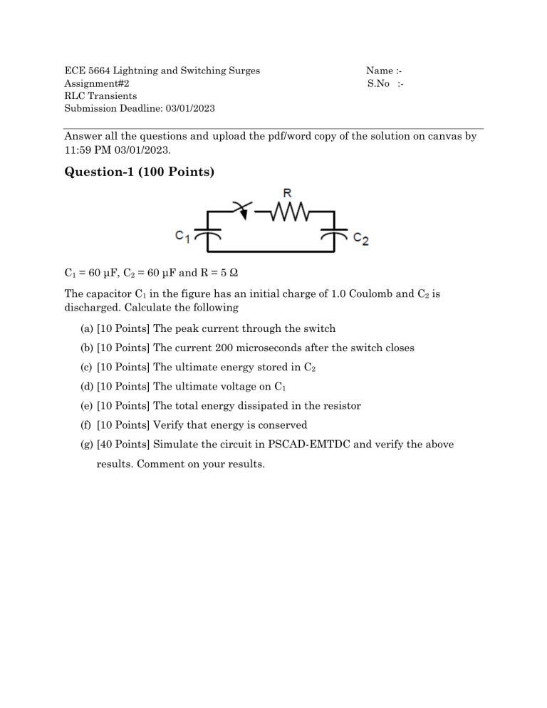
ECE 5664 Lightning and Switching Surges Assignment#2 RLC Transients Submission Deadline: 03/01/2023 Name :S.No :- Answer all the questions and upload the pdf/word copy of the solution on canvas by 11:59 PM 03/01/2023. Question-1 (100 Points) C1 = 60 μF, C2 = 60 μF and R = 5 Ω The capacitor C1 in the figure has an initial charge of 1.0 Coulomb and C2 is discharged. Calculate the following (a) [10 Points] The peak current through the switch (b) [10 Points] The current 200 microseconds after the switch closes (c) [10 Points] The ultimate energy stored in C2 (d) [10 Points] The ultimate voltage on C1 (e) [10 Points] The total energy dissipated in the resistor (f) [10 Points] Verify that energy is conserved (g) [40 Points] Simulate the circuit in PSCAD-EMTDC and verify the above results. Comment on your results. Question-2 (80 Points) Determine the following for the LC circuit shown below with the given conditions C1 = 60 μF, C2 = 40 μF, QC1 = 1C, QC2 = 0C, X = 5 Ω (a) [10 Points] Find the instantaneous current when the switch closes. (b) [10 Points] Determine the peak current (c) [10 Points] Find the energy stored in the inductor at t = 1ms (d) [10 Points] Find the voltage across C1 at t = 1 ms (e) [40 Points] Simulate the circuit in PSCAD-EMTDC and verify the above results. Comment on your results. Question-3 (80 Points) The figure below shows the field coil of an electric machine. It is excited by closing switch S1 onto an 800V d.c. bus. (a) [20 Points] Determine the energy stored in the coil, and the energy dissipated in the coil resistance, 1 sec after S1 is closed. (b) [20 Points] When the coil current has attained a steady value, S1 is opened and S2 is closed simultaneously. What will be the voltage across S1 0.1 sec later? How much energy will eventually be dissipated in R2? (c) [40 Points] Simulate the circuit in PSCAD-EMTDC and verify the above results. Comment on your results. R2 = 10 Ω, RF = 3.6 Ω and LF = 2H The system should be in steady state before opening S1 When simulating the circuit, S1 should be setup to interrupt the steady-state load current S2 needs to be commanded to close at the same time S1 opens. Question-4 (80 Points) A 230kV:69kV, 100 MVA three phase transformer (wye grounded-wye grounded) has per unit leakage reactance of 10% with an X/R ratio of 15. This is supplied by a source impedance of j0.05pu. No change of base calculations are needed. (a) [30 Points] Calculate the worst case peak fault current for a fault at the low voltage terminals. What is the angle of inception compared to the voltage waveform (assume a cosine voltage source)? Include the resistance. (b) [40 Points] Model the system referred to the low voltage winding for your simulation in PSCAD-EMTDC, do not use the built-in transformer models yet. (c) [10 Points] Using simulation only, repeat part A if the X/R ratio of the transformer is 7.


