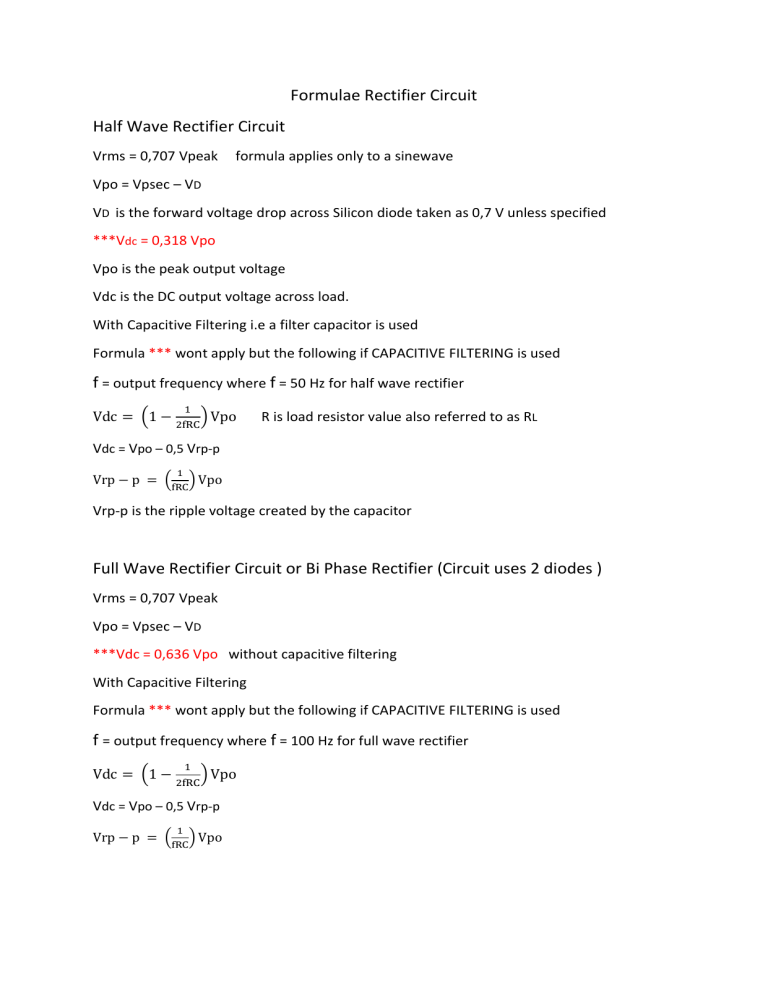
Formulae Rectifier Circuit Half Wave Rectifier Circuit Vrms = 0,707 Vpeak formula applies only to a sinewave Vpo = Vpsec – VD VD is the forward voltage drop across Silicon diode taken as 0,7 V unless specified ***Vdc = 0,318 Vpo Vpo is the peak output voltage Vdc is the DC output voltage across load. With Capacitive Filtering i.e a filter capacitor is used Formula *** wont apply but the following if CAPACITIVE FILTERING is used f = output frequency where f = 50 Hz for half wave rectifier 1 Vdc = (1 − 2fRC) Vpo R is load resistor value also referred to as RL Vdc = Vpo – 0,5 Vrp-p 1 Vrp − p = (fRC) Vpo Vrp-p is the ripple voltage created by the capacitor Full Wave Rectifier Circuit or Bi Phase Rectifier (Circuit uses 2 diodes ) Vrms = 0,707 Vpeak Vpo = Vpsec – VD ***Vdc = 0,636 Vpo without capacitive filtering With Capacitive Filtering Formula *** wont apply but the following if CAPACITIVE FILTERING is used f = output frequency where f = 100 Hz for full wave rectifier 1 Vdc = (1 − 2fRC) Vpo Vdc = Vpo – 0,5 Vrp-p 1 Vrp − p = (fRC) Vpo Bridge Rectifier Circuit ( 4 diodes) Vrms = 0,707 Vpeak Vpo = Vpsec – 2VD ***Vdc = 0,636 Vpo without capacitive filtering Formula *** wont apply but the following if CAPACITIVE FILTERING is used f = output frequency where f = 100 Hz for bridge rectifier circuit 1 Vdc = (1 − 2fRC) Vpo Vdc = Vpo – 0,5 Vrp-p 1 Vrp − p = (fRC) Vpo
