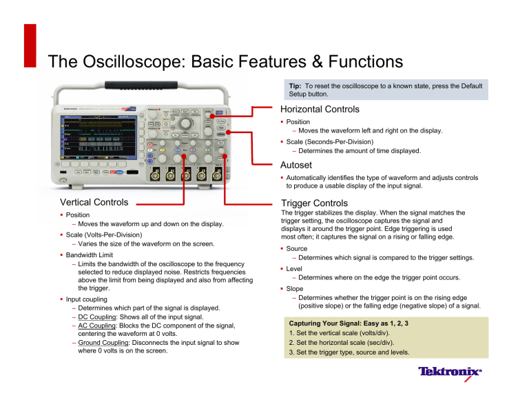
The Oscilloscope: Basic Features & Functions Tip: To reset the oscilloscope to a known state, press the Default Setup button. Horizontal Controls Position – Moves the waveform left and right on the display. Scale (Seconds-Per-Division) – Determines the amount of time displayed. Autoset Automatically identifies the type of waveform and adjusts controls to produce a usable display of the input signal. Vertical Controls Trigger Controls Position – Moves the waveform up and down on the display. The trigger stabilizes the display. When the signal matches the trigger setting, the oscilloscope captures the signal and displays it around the trigger point. Edge triggering is used most often; it captures the signal on a rising or falling edge. Scale (Volts-Per-Division) – Varies the size of the waveform on the screen. Bandwidth Limit – Limits the bandwidth of the oscilloscope to the frequency selected to reduce displayed noise. Restricts frequencies above the limit from being displayed and also from affecting the trigger. Input coupling – Determines which part of the signal is displayed. – DC Coupling: Shows all of the input signal. – AC Coupling: Blocks the DC component of the signal, centering the waveform at 0 volts. – Ground Coupling: Disconnects the input signal to show where 0 volts is on the screen. Source – Determines which signal is compared to the trigger settings. Level – Determines where on the edge the trigger point occurs. Slope – Determines whether the trigger point is on the rising edge (positive slope) or the falling edge (negative slope) of a signal. Capturing Your Signal: Easy as 1, 2, 3 1. Set the vertical scale (volts/div). 2. Set the horizontal scale (sec/div). 3. Set the trigger type, source and levels. The Oscilloscope: Basic Features & Functions Acquisition Modes Advanced Triggering Determine how the oscilloscope digitizes the signal before displaying it. Typically chosen in the “Acquire” menu. Sample: Samples are taken in evenly spaced intervals to construct the waveform. This mode accurately represents signals most of the time. Auto Mode: The oscilloscope sweeps, even without a trigger. Peak Detect: The highest and lowest values of the input signal are captured and used to construct the waveform. This mode will capture narrow pulses that may be missed in Sample Mode. Normal Mode: The oscilloscope only sweeps if the input signal reaches the set trigger point; otherwise the last acquired waveform remains on the display. Single Sequence Mode: After a trigger is detected, the oscilloscope acquires and displays one waveform. Average: Several waveforms are acquired and averaged point-bypoint to obtain the average voltage at each time sample in the acquisition. This mode is used to reduce random noise. Oscilloscope Display Features Trigger point Tip: Indicators for each channel are color-coded Channel 1 waveform (yellow) Trigger level indicator (Channel 1 is the trigger source since indicator is yellow) Ground level indicator (color-coded) Channel 2 waveform (blue) Trigger source & level Trigger frequency readout Vertical scale readout (color-coded) Horizontal scale readout www.tektronix.com/oscilloscopes ©2009 Tektronix, Inc. This document may be reprinted, modified and distributed in whole or in part for the limited purpose of training users or prospective users of Tektronix oscilloscopes and instrumentation. Any reproduction must include a copy of this page containing this notice. 6/09 GB/WWW 3GW-24332-0_ppt

