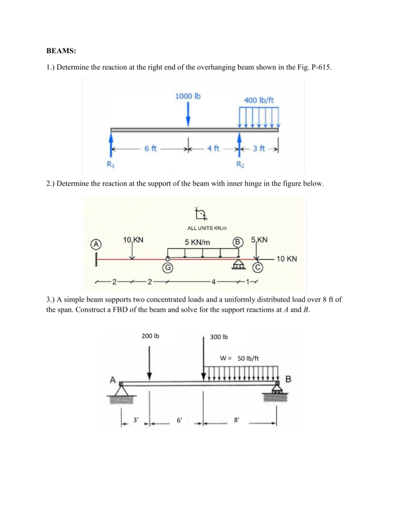
BEAMS: 1.) Determine the reaction at the right end of the overhanging beam shown in the Fig. P-615. 2.) Determine the reaction at the support of the beam with inner hinge in the figure below. 3.) A simple beam supports two concentrated loads and a uniformly distributed load over 8 ft of the span. Construct a FBD of the beam and solve for the support reactions at A and B. 200 lb 300 lb 50 lb/ft 3’ 6’ 8’ 4.) Determine the reaction at the supports of the beam shown below. 5.) Determine the components of the support reactions at the fixed support A on the cantilevered beam. FRAMES: 1.) The frame shown in Figure P-444 is supported by a hinge at A and a roller at E. Compute the horizontal and vertical components of the hinge forces at B and C as they act upon member AC. 2.) In the structure shown in Fig. P-006, all members are assumed to be solid rigid members. The system is pinned to the wall at point A and supported by a roller at point E. Calculate the force on member BD and the reactions at A and E. 3.) Determine the reactions at the supports A and B. The joints C and D are fixed connected. 4.) Determine the reactions at the supports for the frame shown. 5.) Determine the force in members FD and DB of the frame. Also, find the horizontal and vertical components of reaction the pin at C exerts on member ABC and member EDC. TRUSSES: 1.) Find the force acting in all members of the truss shown in Fig. T-01. 2.) Compute the force in all members of the truss shown in Fig. T-08. 3.) Determine the force in each member of the roof truss. State if the members are in tension or compression. Assume B is a pin and C is a roller support. 4.) Determine the force in each member of the truss. State if the members are in tension or compression. Assume all members are pin connected. 5.) Determine the force in each member of the truss. State if the members are in tension or compression. Assume all members are pin connected. AG=GF=FE=ED.


