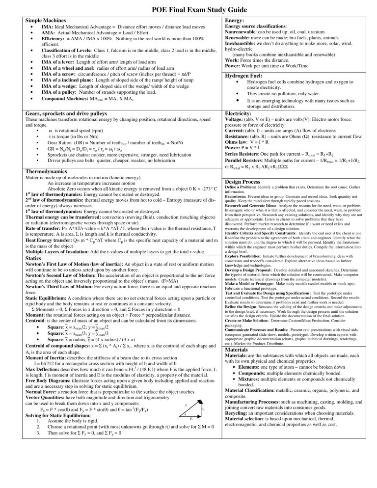
POE Final Exam Study Guide Simple Machines • • • • • • • • • • • Energy: IMA: Ideal Mechanical Advantage = Distance effort moves / distance load moves AMA: Actual Mechanical Advantage = Load / Effort Efficiency: = AMA / IMA x 100% Nothing in the real world is more than 100% efficient. Classification of Levels: Class 1, fulcrum is in the middle, class 2 load is in the middle, class 3 effort is in the middle IMA of a lever: Length of effort arm/ length of load arm IMA of a wheel and axel: radius of effort arm/ radius of load arm IMA of a screw: circumference / pitch of screw (inches per thread) = πd/P IMA of a inclined plane: Length of sloped side of the ramp/ height of ramp IMA of a wedge: Length of sloped side of the wedge/ width of the wedge IMA of a pulley: Number of strands supporting the load. Compound Machines: MAtotal = MA1 X MA2 Energy source classifications: Nonrenewable: can be used up; oil, coal, uranium. Renewable: more can be made; bio fuels, plants, animals Inexhaustible: we don’t do anything to make more; solar, wind, hydro-electric (many books combine inexhaustible and renewable) Work: Force times the distance. Power: Work per unit time or Work/Time Hydrogen Fuel: • • • Hydrogen fuel cells combine hydrogen and oxygen to create electricity. They create no pollution, only water. It is an emerging technology with many issues such as storage and distribution. Gears, sprockets and drive pulleys Electricity: These machines transform rotational energy by changing position, rotational directions, speed and torque. ω is rotational speed (rpm) • • τ is torque (in lbs or Nm) • Gear Ration (GR) = Number of teethout / number of teethin. = No/Ni • GR = No/Ni = Do/Di = τo / τi = ωi / ωo • Sprockets use chains: noisier, more expensive, stronger, need lubrication • Driver pulleys use belts: quieter, cheaper, weaker, no lubrication Voltage: (abb. V or E) – units are volts(V): Electro motor force: pressure or force of electricity Current: (abb. I) – units are amps (A) flow of electrons Resistance: (abb. R) – units are Ohms (Ω): resistance to current flow Ohms law: V = I * R Power: P = V * I Series Resisters: One path for current – Rtotal = R1+R2 Parallel Resisters: Multiple paths for current – 1/Rtotal = 1/R1+1/R2 or Rtotal = R1 x R2 /(R1+R2)ΣΣΣ Thermodynamics Matter is made up of molecules in motion (kinetic energy) An increase in temperature increases motion Absolute Zero occurs when all kinetic energy is removed from a object 0 K = -273° C st 1 law of thermodynamics: Energy cannot be created or destroyed. 2nd law of thermodynamics: thermal energy moves from hot to cold – Entropy (measure of disorder of energy) always increases. 1st law of thermodynamics: Energy cannot be created or destroyed. Thermal energy can be transferred: convection (moving fluid), conduction (touching objects) or radiation (electromagnetic waves through space or air). Rate of transfer: P= A*∆T/r-value = k*A *∆T / L where the r-value is the thermal resistance, T is temperature, A is area, L is length and k is thermal conductivity. Heat Energy transfer: Q= m * Cp*∆T where Cp is the specific heat capacity of a material and m is the mass of the object Multiple Layers of Insulation: Add the r-values of multiple layers to get the total r-value. Statics Newton’s First Law of Motion (law of inertia): An object in a state of rest or uniform motion will continue to be so unless acted upon by another force. Newton’s Second Law of Motion: The acceleration of an object is proportional to the net force acting on the object and inversely proportional to the object’s mass. (F=MA) Newton’s Third Law of Motion: For every action force, there is an equal and opposite reaction force. Static Equilibrium: A condition where there are no net external forces acting upon a particle or rigid body and the body remains at rest or continues at a constant velocity. Σ Moments = 0, Σ Forces in x direction = 0, and Σ Forces in y direction = 0 Moment: the rotational forces acting on an object = Force * perpendicular distance. Centroid: is the center of mass of an object and can be calculated from its dimensions. • Square: x = xmax/2; y = ymax/2 • Square: x = xmax/3; y = ymax/3 • Square: x = radius; y = (4 x radius) / (3 x π) Centroid of compound shapes: x = Σ (xi * Ai) / Σ xi , where xi is the centroid of each shape and Ai is the area of each shape. Moment of Inertia: describes the stiffness of a beam due to its cross section I = bh3/12 for a rectangular cross section with height of h and width of b Max Deflection: describes how much it can bend = FL3 / (48 E I) where F is the applied force, L is length, I is moment of inertia and E is the modulus of elasticity, a property of the material. Free Body Diagrams: illustrate forces acting upon a given body including applied and reaction and are a necessary step in solving for static equilibrium. Normal Force: a reaction force that is perpendicular to the surface the object touches. Vector Quantities: have both magnitude and direction and trigonometry can be used to break them down into x and y components. F F Fx = F * cos(θ) and Fy = F * sin(θ) and θ = tan-1(Fy/Fx) θ Solving for Static Equilibrium: F 1. Assume the body is rigid. 2. Choose a rotational point (with most unknowns go through it) and solve for Σ M = 0 3. Then solve for Σ Fx = 0, and Σ Fy = 0 y x Design Process Define a Problem: Identify a problem that exists. Determine the root cause. Gather information. Brainstorm: Present ideas in group. Generate and record ideas. Seek quantity not quality. Keep the mind alert through rapidly paced sessions. Research and Generate Ideas: Analyze the reasons for the need, want, or problem. Investigate who or what it is that is affected, and consider the need, want, or problem from their perspective. Research any existing solutions, and identify why they are not adequate or appropriate. Listen to clients to solve problems that they have discovered. Perform market research to determine if a want or need exists and warrants the development of a design solution. Identify Criteria and Specify Constraints: Identify the end user if the client is not. Redefine the problem to the agreement of both client and engineer. Identify what the solution must do, and the degree to which it will be pursued. Identify the limitations within which the engineer must perform his/her duties. Compile the information into a design brief. Explore Possibilities: Initiate further development of brainstorming ideas with constraints and tradeoffs considered. Explore alternative ideas based on further knowledge and technologies. Develop a Design Proposal: Develop detailed and annotated sketches. Determine the type(s) of material from which the solution will be constructed. Make computer models. Create technical drawings from the computer model(s). Make a Model or Prototype: Make study models (scaled models or mock-ups). Fabricate a functional prototype. Test and Evaluate the Design using Specifications: Test the prototype under controlled conditions. Test the prototype under actual conditions. Record the results. Evaluate results to determine if problems exist and further work is needed. Refine the Design: Reassess the validity of the design criteria and make adjustments to the design brief, if necessary. Work through the design process until the solution satisfies the design criteria. Update the documentation of the final solution. Create or Make Solution: Determine Custom/Mass Production. Consider packaging. Communicate Processes and Results: Present oral presentations with visual aids (computer generated slide show, models, prototype). Develop written reports with appropriate graphic documentation (charts, graphs, technical drawings, renderings, etc.). Market the Product. Distribute. Materials Materials: are the substances with which all objects are made, each with its own physical and chemical properties. • Elements: one type of atom – cannot be broken down • Compounds: multiple elements chemically bonded. • Mixtures: multiple elements or compounds not chemically bonded. Material Classification: metallic, ceramic, organic, polymeric, and composite. Manufacturing Processes: such as machining, casting, molding, and joining convert raw materials into consumer goods. Recycling: an important considerations when choosing materials. Material selection: is based upon mechanical, thermal, electromagnetic, and chemical properties as well as cost. Materials Testing Tensile Stress Test: Measures the deformation and breaking point of a test sample under static tensile force. Hardness test: Brinell or Rockwell hardness measures a material’s resistance to a probe creating a crater in it. Non-destructive test: properties such as density and conductivity may be tested without damaging the material, but others such as strength and hardness require destructive tests. Stress: (σ) Externally applied – depends on force and material’s shape = F/A for tensile stress. Strain: (ε) material’s response to stress = change in length / original length. Deformation: (δ) elongation - how much the length of a sample changes under stress Elastic range: Linear portion of stress / strain curve. Material isn’t permanently changed. Elastic Limit: (Proportional limit or Yield point) Plastic deformation (permanent change) starts to occur. Resilience: area under the linear portion of the curve. Measure the energy needed to permanently deform the material Ultimate Tensile Strength: maximum tensile stress, the peak of the curve. Ductility: Amount of plasticity before fracture, measures how much the material can be stretched. Modulus of Elasticity: (E) a measure of how much a material resists stretching = σ/ε also = PL/Aδ where P is the axial force, L is the original length, and A is the cross sectional area. Fluid Power Fluid Power: relies on pressure of a liquid or a gas to transmit force over great distances, multiply an input force, and increase the distance that an output will move. Pneumatic Power: uses gas – faster, cleaner, requires a lubricant Hydraulic Power: uses a liquid – stronger, more precise, higher pressure Basic components: of a fluid power systems include a reservoir or receiver, a pump or compressor, a valve, and a cylinder. Pascal’s Law: Pressure is the same everywhere within a non moving system P = F/A Boyle’s Law: Pressure and volume are inversely related P1/P2 =V2/V1 Charles’ Law: temperature and volume are directly related T1/T2 =V1/V2 Gay-Lussac’s Law: Pressure and temperature are directly related P1/P2 = T1/T2 Absolute Pressure: = measured pressure + atmospheric pressure (14.7 psi at sea level) – always use this when applying Boyle’s law or Gay-Lussac’s Law. Absolute Temperature: = Temperature above absolute zero = 460° + °F or 273° + °C – always use this when applying Charles’ law or Gay-Lussac’s Law. Control Systems Kinematics Flow Chart: a graphical representation of a program. • Rectangle: process or action • Rounded Rectangle: start or end • Parallelogram: input (from real world to program) or output (from program to the real world) • Rhombus: decision or a branch Open Loop: No feedback, relies on timing, un-repeatable Closed Loop: feedback tells program it is done, more repeatable Normally open: no connection until switch is pressed Normally closed: connection until switch is pressed Displacement: straight line distance and direction from initial point Speed: a scalar quantity describing distance traveled / time Velocity: a vector quantity with both speed and direction Acceleration: a change in velocity per unit time. Gravity: will cause a constant acceleration (ignoring air resistance) of -32.2 ft /sec 2 or -9.8 m/sec2 Projectile: a non-powered object moving through the air – its final displacement can be calculated from its initial velocity. Its x component of velocity is constant while the y component changed due to gravity. X=vi2 * sin (2* θ )/ -g Statistics Experimental Data: always has some error – large samples can be characterized using statistics. Centrality measures: Mean (sum/# of samples), median (middle value) or mode (most common value) gives us an idea of the true value. Variability measures: range and standard deviation give us an idea of how repeatable our measure are
