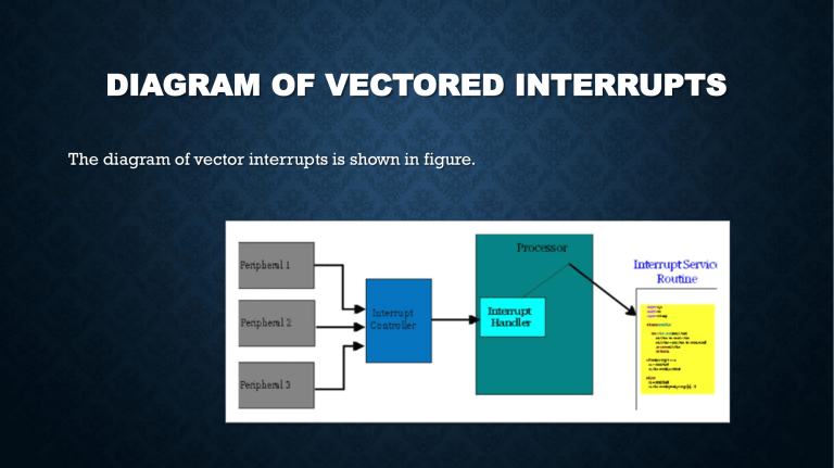
DIAGRAM OF VECTORED INTERRUPTS The diagram of vector interrupts is shown in figure. EXPLANATION OF DIAGRAM When the user program is executed and suppose an interrupt occur then the CPU have to execute a service routine to provide service to the interrupt. So when the ISR execute it return back to the CPU for the next instruction. So, the way the processor(CPU) chooses the branch address of interrupt service Routine (ISR) varies from one unit to another. There are to methods, Vector interrupt Non-vector interrupt VECTORED INTERRUPTS • A vectored interrupt is where the CPU knows the address of the Interrupt Service Routine in advance. • In a computer, a vectored interrupt is an I/O interrupt that tells the part of the computer that handles I/O interrupts at the hardware level that a request for attention from an I/O device has been received and and also identifies the device that sent the request.For example: RST7. 5, RST6. .. NON VECTORED INTERRUPTS • Non-Vectored Interrupts are those in which vector address is not predefined. The interrupting device gives the address of sub-routine for these interrupts. For example, INTR.... DIFFERENCE Vector interrupt • The ISR address of this interrupts is known to CPU. • The ISR address of this interrupts is fixed. • The microprocessor jumps to the specific service routine. • When the microprocessor executes the call instruction, it saves the address of the next instruction on the stack. • At the end of the service routine, the RET instruction returns the execution to where the program was interrupted. • All 8051 interrupts are vectored interrupts. Non-vector interrupt • Address of this common ISR is known to the CPU. • The interrupts which don’t have fixed memory location for transfer of control from normal execution. • The address of the memory is sent along with the interrupt.. • Once the interrupt occurs, the system must determine which device, of all the devices associated actually interrupted. VECTOR INTERRUPT • A vectored interrupt is where the CPU knows the address of the interrupt service routine in advance. All it needs is that the interrupting device sends its unique vector through a data bus and through its I/O interface to the CPU. The CPU takes this vector, checks an interrupt table in memory and then carries out the correct ISR for that device. Therefore, the vectored interrupt allows the CPU to be able to know that ISR to carry out in software (memory) NON VECTOR INTERRUPT • A non–vectored interrupt is where the interrupting device never sends an interrupt vector. An interrupt is received by the CPU and it jumps the program counter to a fixed address in hardware. • In an Interrupt Structure of 8086 system the first 1 Kbyte of memory from 00000H to 003FFH is reserved for storing the starting addresses of interrupt service routines. • This block of memory is often called the Interrupt Vector Table in 8086 or the interrupt pointer table. • Since 4 bytes are required to store the CS and IP values for each interrupt service procedure, the table can hold the starting add. • When the 8086 responds to an interrupt, it automatically goes to the specified location in the Interrupt Vector Table in 8086 to get the starting address of interrupt service routine. • So user has to load these starting addresses for different routines at the start of the program. TYPES • Each interrupt type is given a number between 0 to 255 and the address of each interrupt js found by multiplying the type by 4 e.g. for type 11, interrupt address is 11 x 4 = 4410= 0002CH • Only first five types have explicit definitions such as divide by zero and non maskable interrupt. • The next 27 interrupt types, from 5 to 31, are reserved by Intel for use in future microprocessors. • The upper 224 interrupt types, from 32 to 255, are available for user for hardware or software interrupts. • DETERMINING ADDRESS THROUGH INTERRUPT VECTOR TABLE All interrupts are assigned a number from 0 to 255, with each of these interrupts being associated with a specific interrupt vector. Interrupts 0, 1, 3, 4, 6 and 7 are generated by the processor. Interrupts from 8 to 15 and interrupt 2 are generated by external hardware. Most other interrupts are generated by software. • The first two bytes store the offset and the next two store the segment address. • To find the vector for an interrupt routines, we simply multiply it by 4. • INT n. Here, n is the type number. CONT. • Then we get memory location of Offset Address= n*4 • The segment address is in the next word. • Memory location of Segment address= Memory Location of Offset address+2 • With memory location obtained by this formulae, we search for Offset : Segment addresses in IVT. Through these we can find physical address of interrupt routines. Vector diagram Vector and non-vectors Difference Vector interrupt table Determine the address through table

