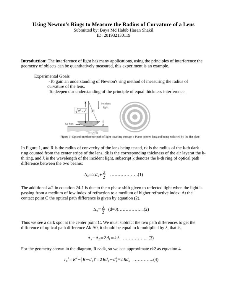
Using Newton's Rings to Measure the Radius of Curvature of a Lens Submitted by: Buya Md Habib Hasan Shakil ID: 201932130119 Introduction: The interference of light has many applications, using the principles of interference the geometry of objects can be quantitatively measured, this experiment is an example. Experimental Goals -To gain an understanding of Newton's ring method of measuring the radius of curvature of the lens. -To deepen our understanding of the principle of equal thickness interference. Figure 1: Optical interference path of light traveling through a Plano-convex lens and being reflected by the flat plate. In Figure 1, and R is the radius of convexity of the lens being tested, rk is the radius of the k-th dark ring counted from the center stripe of the lens, dk is the corresponding thickness of the air layerat the kth ring, and λ is the wavelength of the incident light, subscript k denotes the k-th ring of optical path difference between the two beams: Δ k =2 d k + λ 2 ……………….(1) The additional λ/2 in equation 24-1 is due to the π phase shift given to reflected light when the light is passing from a medium of low index of refraction to a medium of higher refractive index. At the contact point C the optical path difference is given by equation (2). Δ 0= λ (d=0)……………...(2) 2 Thus we see a dark spot at the center point C. We must subtract the two path differences to get the difference of optical path difference Δk-Δ0, it should be equal to k multiplied by λ, that is, Δ k −Δ 0=2 d k =k λ ……………...(3) For the geometry shown in the diagram, R>>dk, so we can approximate rk2 as equation 4. r k 2=R 2−( R−d k )2=2 Rd k −d 2k ≈ 2 Rdk …………..(4) Finally by substituting 2 d k =k λ , that we have from equation 3, we can find the radius from the center dark spot out to the k-th dark ring. r k = √ Rk λ …………..(5) Now if we know the wavelength λ of the light we can use the radii of the Newton’s dark rings to determine the radius of curvature of the convex lens R. In fact, due to contact pressure between the two pieces of glass the glass will distort and contact will not only at one point but over a small area. Also dust can cause the fringe numbers to not be correct in the experimental values of k. This will result in errors in the value of R. To avoid this error, we count ‘n’ rings from the Center to the outside and measure the radius of this ring rn, this can then be compared with the m-th ring radius rm (equation 6) to yield a more accurate measure of the radius of curvature of the lens. 2 2 r n =nR λ , r m =mR λ ……………...(6) Subtracting the two equations we find, 2 2 r m −r n R= ……………...(7) (m−n) λ It is difficult to experimentally determine the exact location of the Newton Center, so it is necessary to measure diameters Dn and Dm instead of measuring radius of rn and rm. This gives us: 2 2 Dm −Dn R= …………...(8) 4 (m−n) λ Equipment: -Reading microscope -Newton's rings apparatus -Sodium lights Procedure: 1) Using the room lights look at the Newton ring apparatus and adjust the box screws so that the interference rings are round and located in the center of the lens. Being careful not too tighten the screws too much. 2) Turning on the monochromatic sodium lamp, this will be the light source we will use for this experiment. Direct the light emitted by the light source ‘S’ onto the glass ‘G’, and direct the light reflected by ‘G’ into the Newton's rings apparatus. Adjusting the height and tilt angle of the glass ‘G’. The yellow bright field of view can be observed in the microscope. 3) Next adjusting the reading microscope eye piece. The cross hairs should be clearly visible in the eyepiece. Pointing the reading microscope at the center of the Newton's rings apparatus and move the tube up and down to focus on the interference fringes so that we can see the rings as clearly as possible. 4) The diameter of the interference ring can be measured by reading the microscope, but the measurements are sometimes vague due to data collection not at the peak of the ring. Therefore it is generally better to measure the diameter difference between more than 3 rings at a time such that (m2-m1)<3. Also from the point of view of reducing measurement error, (m2-m1) should not be too small, so it is better to measure the diameter difference across more than three rings. To avoid hysteresis error we should return the microscope crosshair to the center of the rings after each measurement. This can be done most accurately by moving the crosshair past the center in the opposite direction that we are measuring, and then carefully bring the crosshair back to the center. This will take up the slack in the microscope dial and yield more accurate measurements. Measurements should always be done such that we are rotating the microscope dial in the same direction every time. 5) Calculating the radius of curvature of the Plano-convex lens Rand the standard deviation (uncertainty) in measurements. Result: Dm Dn D −Dn R= m 4 (m−n) λ 35.39 25.88 0.02600594 34.8 27.97 0.02666426 30.24 29.69 0.02543718 2 2
