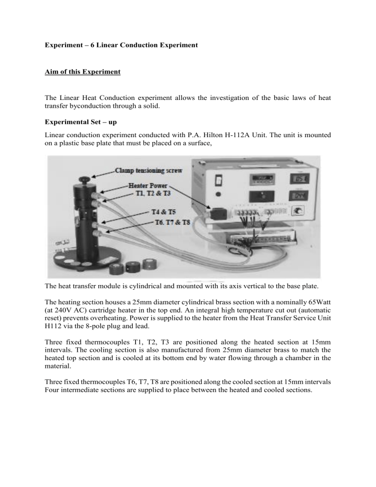
Experiment – 6 Linear Conduction Experiment Aim of this Experiment The Linear Heat Conduction experiment allows the investigation of the basic laws of heat transfer byconduction through a solid. Experimental Set – up Linear conduction experiment conducted with P.A. Hilton H-112A Unit. The unit is mounted on a plastic base plate that must be placed on a surface, The heat transfer module is cylindrical and mounted with its axis vertical to the base plate. The heating section houses a 25mm diameter cylindrical brass section with a nominally 65Watt (at 240V AC) cartridge heater in the top end. An integral high temperature cut out (automatic reset) prevents overheating. Power is supplied to the heater from the Heat Transfer Service Unit H112 via the 8-pole plug and lead. Three fixed thermocouples T1, T2, T3 are positioned along the heated section at 15mm intervals. The cooling section is also manufactured from 25mm diameter brass to match the heated top section and is cooled at its bottom end by water flowing through a chamber in the material. Three fixed thermocouples T6, T7, T8 are positioned along the cooled section at 15mm intervals Four intermediate sections are supplied to place between the heated and cooled sections. The heated section, cooling section and all the intermediate sections are located co-axially inside plastic housings. An annular air gap insulates the specimens from the surroundings and minimise heat losses/gains. The heated and cooled sections incorporate centralising ‘O’ rings to ensure that each are held concentrically. Similar ‘O’ rings are fitted to the intermediate sections so that they are installed in alignment. Toggle clamps ensure that the heated and cooled sections are held tightly together, with or without the intermediate sections installed. Slacken the clamp tensioning screw before releasing the toggle clamps and re-apply tension after fitting a new specimen, thus avoiding over-stressing the clamping device. Water for the cooled section is supplied from a local tap via the supplied hoses. The water flow rate is adjusted by manual control of the supply tap. After cooling the cooled section, The water is allowed to run to a drain via the outlet hose. The four intermediate sections supplied are as follows: Brass Specimen 30mm long, 25mm diameter fitted with two thermocouples T4, T5 at 15mm intervals along the axis. With the brass specimen clamped between the heated and cooled sections a uniform 25mm diameter brass bar is formed with 8 uniformly spaced (15mm intervals) thermocouples (T1 to T8 Stainless Steel Specimen 30mm long, 25mm diameter. No thermocouples fitted Aluminium Specimen 30mm long, 25mm diameter. No thermocouples fitted. Brass Specimen with Reduced Diameter 30mm long, 13mm diameter. No thermocouples fitted. In addition, the heat conducting properties of insulators such as cork and paper may be found by clamping the insulating discs between the heated and cooled sections. The effect of good thermal contact between conducting surfaces is demonstrated by experiments with and without toggle clamps. The value of heat transfer paste may be verified by experiments with and without paste. Schematic Representation of Linear Conduction Experiment Unit Capabilities Of The Linear Heat Transfer Unit 1. To measure the temperature distribution for steady state conduction of energy through a uniform plane wall and demonstrate the effect of a change in heat flow. 2. To understand the use of the Fourier Rate Equation in determining rate of heat flow through solid materials for one dimensional, steady flow of heat. 3. To measure the temperature distribution for steady state conduction of energy through a composite plane wall and determine the Overall Heat Transfer Coefficient for the flow of heat through a combination of different materials in use. 4. To determine the thermal conductivity k of a metal specimen. 5. To demonstrate that the temperature gradient is inversely proportional to the cross-sectional area for one dimensional flow of heat in a solid material of constant thermal conductivity. 6. To demonstrate the effect of contact resistance on thermal conduction between adjacent materials. 7. To understand the application of poor thermal conductors and determine the thermal conductivity k of a poor thermal conductor. 8. To observe unsteady state conduction of heat and to use this in observation of the time to reach stable conditions. Operating Procedure Of Linear Heat Transfer Unit 1. Ensure that the main switch is in the off position (the digital displays should not beilluminated). Ensure that the residual current circuit breaker on the rear panel is in the ONposition. Note that this should be tested for normal operation at intervals specified bylocal regulations using the method described in the MAINTENANCE section. 2. Turn the voltage controller anti-clockwise to set the AC voltage to minimum. Ensure theLinear Heat Transfer Unit H112A has been connected to the Heat Transfer Service Unit H112. 3. Ensure the cold water supply and electrical supply are turned on at the source. Open the watertap until the flow through the drain hose is approximately 1.5 litres/minute. The actual flowcan be checked using a measuring vessel and stopwatch if required but this is not a criticalparameter. The flow has to dissipate up to 65W only. 4. Release the toggle clamp tensioning screw and clamps. Ensure that the faces of the exposedends of the heated and cooled sections are clean. Similarly, check the faces of the intermediatespecimen (if in use) to be placed between the faces of the heated and cooled sections. Ifinstructed in the individual procedures for the experiment, coat the mating faces of theheated and cooled sections and the intermediate section (if used) with thermalconduction paste. Ensure the intermediate section to be used is in the correct orientation thenclamp the assembly together using the toggle clamps and tensioning screw. 5. Turn on the main switch and the digital displays should illuminate. Set the temperatureselector switch to T1 to indicate the temperature of the heated end of the bar. Rotate thevoltage controller to increase the voltage to that specified in the procedure for eachexperiment. 6. Observe the temperature T1. This should begin to increase. 7. Allow the system to reach stability, and take readings and make adjustments as instructed inthe individual procedures for each experiment. 8. When the experimental procedure is completed, it is good practice to turn off the power to theheater by reducing the voltage to zero and allow the system a short time to cool before turningoff the cooling water supply. 9. Ensure that the locally supplied water supply isolation valve to the unit is closed. Turn off themain switch and isolate the electrical supply. 10. Note that if the thermal conducting paste is left on the mating faces of the heated and cooledsections for a long period it can be more difficult to remove than if removed immediately aftercompleting an experiment. If left on the intermediate sections it can attract dust and inparticular grit which acts as a barrier to good thermal contact. Experiment -6.1 To Measure The Temperature Distribution For Steady State Conduction Of Energy Through A Uniform Plane Wall And Demonstrate The Effect Of A Change İn Heat Flow. Aim of this experiment This experiment aims to determine the temperature gradient during linear heat transfer by conduction along the wall. Procedure Following the basic OPERATING PROCEDURE smear the faces of the heated and cooled sections with thermal conducting paste and clamp them together without any intermediate section in place. Schematically this produces a system as shown below. Again following the above procedure ensure the cooling water is flowing and then set the heater voltage V to 90 volts. Monitor temperatures T1, T2, T3, T6, T7, T8 until stable. When the temperatures are stabilised record:T1, T2, T3, T6, T7, T8, V and I. Reset the heater voltage to 120 volts and repeat the above procedure again recording the parameters T1,T2, T3, T6, T7, T8, V and I when temperatures have stabilised. Reset the heater voltage to 170 volts and repeat the above procedure again recording the parameters T1,T2, T3, T6, T7, T8, V and I when temperatures have stabilised. Reset the heater voltage to 200 volts and repeat the above procedure again recording the parameters T1,T2, T3, T6, T7, T8, V and I when temperatures have stabilised. When completed, if no further experiments are to be conducted reduce the heater voltage to zero and shut down the system. Sample Test Results Experiment -6.2 To Understand The Use Of The Fourier Rate Equation İn Determining Rate Of Heat Flow Through Solid Materials For One Dimensional, Steady Flow Of Heat. Aim of this experiment This experiment aims to determine the temperature gradient during linear heat transfer by conduction in steady state condition and different solid materials. Procedure Following the basic OPERATING PROCEDURE smear the faces of the heated and cooled sections with thermal conducting paste and clamp them together with the Brass Intermediate Specimen in place. Schematically this produces a system as shown below. Following the above procedure ensure the cooling water is flowing and then set the heater voltage V to approximately 120 volts. This will provide a reasonable temperature gradient along the length of the bar. If however the local cooling water supply is at a high temperature (25-35 ºC or more) then it may be necessary to increase the voltage supplied to the heater. This will increase the temperature difference between the hot and cold ends of the bar. Monitor temperatures T1, T2, T3, T4, T5, T6, T7, T8 until stable. When the temperatures are stabilised record: T1, T2, T3, T4, T5, T6, T7, T8, V, I Increase the heater voltage by approximately 50 volts and repeat the above procedure again recording the parameters T1, T2, T3, T4, T5, T6, T7, T8, V, I when temperatures have stabilised. When completed, if no further experiments are to be conducted reduce the heater voltage to zero and shut down the system. Sample Test Results Experiment -6.3 To Determine The Thermal Conductivity k Of A Metal Specimen. Aim of this experiment This experiment aims to determine thermal conductiviy of different metals. Procedure Following the basic OPERATING PROCEDURE smear the faces of the heated and cooled sections with thermal conducting paste and clamp them together with the aluminium intermediate section in place. Schematically this produces a system as shown below Following the above procedure ensure the cooling water is flowing and then set the heater voltage V to approximately 150 volts. This will provide a reasonable temperature gradient along the length of the bar. If however the local cooling water supply is at a high temperature (25-35 ºC or more) then it may be necessary to increase the voltage supplied to the heater. This will increase the temperature difference between the hot and cold ends of the bar. Monitor temperatures T1, T2, T3, T6, T7, T8 until stable. When the temperatures are stabilised record: T1, T2, T3, T6, T7, T8, V, I Increase the heater voltage by approximately 50 volts and repeat the above procedure again recording the parameters T1, T2, T3, T6, T7, T8, V, I when temperatures have stabilised. When completed, if no further experiments are to be conducted reduce the heater voltage to zero and shut down the system. Sample Test Results Theory of Experiments If the heated and cooled surfaces are clamped tightly together and are in good thermal contact, then the two sections can be considered as a continuous homogenous sample of uniform cross section and material. According to Fourier’s law of heat conduction: If a plane section of thickness Δx and constant area A maintains a temperature difference ΔT then theheat transfer rate per unit time Q by conduction through the wall is found to be: Where, C is a constant that will be examined at a later stage. Overleaf are sample test results and illustrative calculations showing the application of the above theory. If a plane section of thickness Δx and constant area A maintains a temperature difference ΔT then the heat transfer rate per unit time Q by conduction through the wall is found to be: Where and If the material of the wall is homogeneous and has a thermal conductivity k then The negative sign follows thermodynamic convention in that heat transfer is normally considered positive in the direction of temperature fall. However, for the purposes of the following illustrations the negative sign will be ignored. Overleaf are sample test results and illustrative calculations showing the application of the above theory. If the heated and cooled sections are clamped tightly together so that the end faces are in good thermal contact with the stainless steel intermediate section a composite bar of the form shown below is formed. Assuming that the energy entering the heated end is conducted without loss to the surroundings through to the cooled end the heat flow through each section must be equal. Hence by applying Fourier’s law to the Aluminium centre section where By re-arranging the formula the thermal conductivity kint of the intermediate section can be calculated from: Overleaf are sample test results and illustrative calculations showing the application of the above theory. Appendix – I Symbolas and Units Appendix – II Some Useful Data
