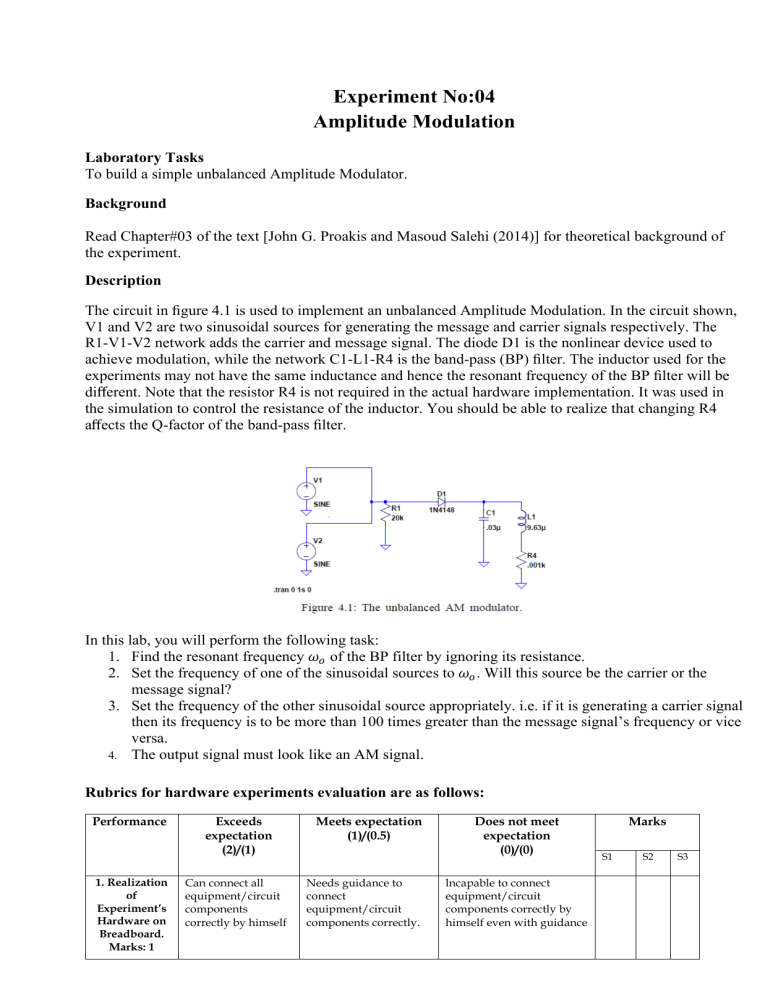
Experiment No:04 Amplitude Modulation Laboratory Tasks To build a simple unbalanced Amplitude Modulator. Background Read Chapter#03 of the text [John G. Proakis and Masoud Salehi (2014)] for theoretical background of the experiment. Description The circuit in figure 4.1 is used to implement an unbalanced Amplitude Modulation. In the circuit shown, V1 and V2 are two sinusoidal sources for generating the message and carrier signals respectively. The R1-V1-V2 network adds the carrier and message signal. The diode D1 is the nonlinear device used to achieve modulation, while the network C1-L1-R4 is the band-pass (BP) filter. The inductor used for the experiments may not have the same inductance and hence the resonant frequency of the BP filter will be different. Note that the resistor R4 is not required in the actual hardware implementation. It was used in the simulation to control the resistance of the inductor. You should be able to realize that changing R4 affects the Q-factor of the band-pass filter. In this lab, you will perform the following task: 1. Find the resonant frequency 𝜔𝑜 of the BP filter by ignoring its resistance. 2. Set the frequency of one of the sinusoidal sources to 𝜔𝑜 . Will this source be the carrier or the message signal? 3. Set the frequency of the other sinusoidal source appropriately. i.e. if it is generating a carrier signal then its frequency is to be more than 100 times greater than the message signal’s frequency or vice versa. 4. The output signal must look like an AM signal. Rubrics for hardware experiments evaluation are as follows: Performance 1. Realization of Experiment’s Hardware on Breadboard. Marks: 1 Exceeds expectation (2)/(1) Can connect all equipment/circuit components correctly by himself Meets expectation (1)/(0.5) Needs guidance to connect equipment/circuit components correctly. Does not meet expectation (0)/(0) lncapable to connect equipment/circuit components correctly by himself even with guidance Marks S1 S2 S3 2. Knowledge of theoretical aspects: 1 Has required knowledge 3. Conducting Hardware Experiment. Marks: 2 Does proper calibration of equipment and ensures smooth experimental process without guidance Correct results are displayed 4. Displaying proper results. Marks: 1 S1, S2 and S3 are members of a group. Has no or partial knowledge Needs guidance for proper calibration of equipment or to ensures smooth operation of experiment Unable to calibrate appropriate equipment or to ensure smooth operation of experiment even with guidance Results are with minor errors Results are with major errors
