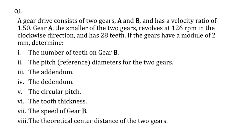
Q1. A gear drive consists of two gears, A and B, and has a velocity ratio of 1.50. Gear A, the smaller of the two gears, revolves at 126 rpm in the clockwise direction, and has 28 teeth. If the gears have a module of 2 mm, determine: i. The number of teeth on Gear B. ii. The pitch (reference) diameters for the two gears. iii. The addendum. iv. The dedendum. v. The circular pitch. vi. The tooth thickness. vii. The speed of Gear B. viii.The theoretical center distance of the two gears. Q2. The spur gear arrangement made for transmitting 3.2 kW power as shown in Figure Q2 has a pinion (driver Gear A) that rotates at 625 rpm, an idler Gear B and a driven gear (Gear C). The gears have a module of 5 mm and a pressure angle of 200. Given the number of teeth as shown in Figure Q2, determine: i. The pitch diameters of each of the gears. ii. The torque that each shaft is required to transmit. iii. The forces on each of the gears, shown on a free body diagram. iv. The resultant force on the shaft carrying Gear B. Q3. The set of double-reduction gears shown in Figure Q3, is driven by a pinion (Gear A) with a module of 1.5 mm, which rotates at 3600 rpm and has a pitch-line velocity of 4.52 ms-1. The second set of gears (Gears C and D) has a pitch-line velocity of 0.78 ms-1 and a module of 2.5 mm. Given that the reduction ratio between the Gears A and B is to be 12:1, and the reduction ratio between Gears C and D is to be 10:1, determine: i. The number of teeth on each of the gears. ii. The speed of Gears B, C, and D. iii. The center distances for Gears A and B, and Gears C and D. Q4. Based on the gear arrangement shown in Figure Q3, and for an input power of 4.25 kW, determine the forces on each of the gears assuming that the pressure angle is 200, and show these on a free body diagram.


![Machine Elements [Opens in New Window]](http://s3.studylib.net/store/data/009054465_1-76bd66345967cd60934cd86eccae6fad-300x300.png)
