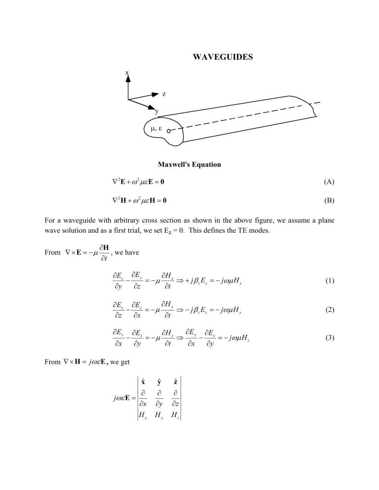
WAVEGUIDES x z y Maxwell's Equation 2E 2 E 0 (A) 2 H 2 H 0 (B) For a waveguide with arbitrary cross section as shown in the above figure, we assume a plane wave solution and as a first trial, we set Ez = 0. This defines the TE modes. From E H , we have t H x Ez E y j z E y j H x y z t (1) H y Ex Ez j z Ex j H y z x t (2) E y x E y Ex Ex H z j H z y t x y From H j E , we get xˆ j E x Hx yˆ y Hy zˆ z Hz (3) -2- H z H y H z j Ex j z H y j Ex y z y (4) H x H z H z j E y j z H x j E y z x x (5) H y x H x 0 y (6) We want to express all quantities in terms of Hz. From (2), we have Hy z Ex (7) in (4) E H z j z2 x j Ex y (8) Solving for Ex Ex j H z 2 y 2 z (9) From (1) Hx z Ey (10) in (5) j z2 E y H z j E y x (11) j H z 2 x (12) so that Ey 2 z -3- Hx j z H z 2 x (13) Hy j z H z 2 y (14) 2 z 2 z Ez = 0 (15) Combining solutions for Ex and Ey into (3) gives 2 H z 2 H z z2 2 H z x 2 y 2 (16) RECTANGULAR WAVEGUIDES y x z b a If the cross section of the waveguide is a rectangle, we have a rectangular waveguide and the boundary conditions are such that the tangential electric field is zero on all the PEC walls. TE Modes The general solution for TE modes with Ez=0 is obtained from (16) j y j y H z e j z z Ae j x x Be j x x Ce y De y Ey Ex (17) x j y j y De e j z Ae j x Be j x Ce 2 z x x y y 2 z y 2 z At y=0, Ex=0 which leads to C=D At x=0, Ey=0 which leads to A=B 2 j y j y e j z z Ae j x x Be j x x Ce y De y (18) (19) -4- H z H o e j z z cos x x cos y y Ey Ex (20) j x H o e j z z sin x x cos y y 2 2 z j y 2 z 2 At x=a, Ey=0; this leads to x m a At y=b, Ex=0; this leads to y n b H o e j z z cos x x sin y y (21) (22) The dispersion relation is obtained by placing (20) in (16) x2 y2 z2 2 2 (23) 2 m n 2 2 z a b (24) and 2 m n a b 2 z 2 (25) The guidance condition is 2 m n 2 a b 2 (26) or f > fc where fc is the cutoff frequency of the TEmn mode given by the relation fc 1 2 2 m n a b 2 (27) The TEmn mode will not propagate unless f is greater than fc. Obviously, different modes will have different cutoff frequencies. -5TM Modes The transverse magnetic modes for a general waveguide are obtained by assuming Hz =0. By duality with the TE modes, we have 2 Ez 2 E z 2 z2 2 Ez 2 x y (28) with general solution Ez e j z z Ae j x x Be j x x Ce j y y De j y y (29) The boundary conditions are At x=0, Ez=0 which leads to A=-B At y=0, Ez=0 which leads to C=-D At x=a, Ez=0 which leads to x m a At y=b, Ez=0 which leads to y n b so that the generating equation for the TMmn modes is Ez Eo e j z z sin x x sin y y (30) NOTE: THE DISPERSION RELATION, GUIDANCE CONDITION AND CUTOFF EQUATIONS FOR A RECTANGULAR WAVEGUIDE ARE THE SAME FOR TE AND TM MODES. For additional information on the field equations see Rao (6th Edition), page 607, Table 9.1. There is no TE00 mode There are no TMm0 or TM0n modes The first TE mode is the TE10 mode The first TM mode is the TM11 mode -6Impedance of a Waveguide For a TE mode, we define the transverse impedance as gTE Ey Hx Ex H y z From the relationship for z and using 2 2 1 m n f 4 a b 2 c (31) we get gTE (32) f2 1 c2 f where is the intrinsic impedance gTM 1 Analogously, for TM modes, it can be shown that f c2 f2 (33) Power Flow in a Rectangular Waveguide (TE10) The time-average Poynting vector for the TE10 mode in a rectangular waveguide is given by 2 E z 1 x sin 2 P Re E× H* zˆ o 2 2 a Power a 0 b 0 2 2 z x sin 2 dxdy 2 a Eo (34) (35) 2 E z ab Eo ab Power o 4 4 gTE10 (36) Therefore, the time-average power flow in a waveguide is proportional to its cross-section area.

