Synchronous Close vs. CapSwitcher: Capacitor Switching Tech
advertisement

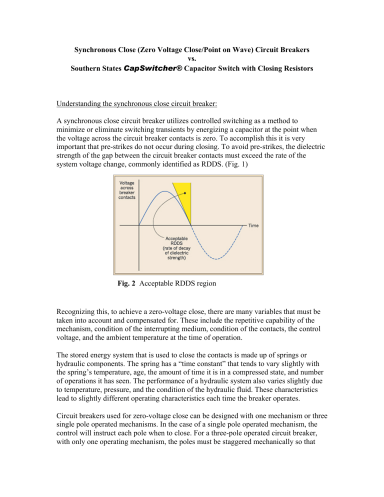
Synchronous Close (Zero Voltage Close/Point on Wave) Circuit Breakers vs. Southern States CapSwitcher® Capacitor Switch with Closing Resistors Understanding the synchronous close circuit breaker: A synchronous close circuit breaker utilizes controlled switching as a method to minimize or eliminate switching transients by energizing a capacitor at the point when the voltage across the circuit breaker contacts is zero. To accomplish this it is very important that pre-strikes do not occur during closing. To avoid pre-strikes, the dielectric strength of the gap between the circuit breaker contacts must exceed the rate of the system voltage change, commonly identified as RDDS. (Fig. 1) Fig. 2 Acceptable RDDS region Recognizing this, to achieve a zero-voltage close, there are many variables that must be taken into account and compensated for. These include the repetitive capability of the mechanism, condition of the interrupting medium, condition of the contacts, the control voltage, and the ambient temperature at the time of operation. The stored energy system that is used to close the contacts is made up of springs or hydraulic components. The spring has a “time constant” that tends to vary slightly with the spring’s temperature, age, the amount of time it is in a compressed state, and number of operations it has seen. The performance of a hydraulic system also varies slightly due to temperature, pressure, and the condition of the hydraulic fluid. These characteristics lead to slightly different operating characteristics each time the breaker operates. Circuit breakers used for zero-voltage close can be designed with one mechanism or three single pole operated mechanisms. In the case of a single pole operated mechanism, the control will instruct each pole when to close. For a three-pole operated circuit breaker, with only one operating mechanism, the poles must be staggered mechanically so that they will close at the right time. For a grounded capacitor bank on a 60 Hz system, each pole would be staggered to close 600 following the last pole to close. As stated above, the dielectric strength across the breaker contacts must exceed the system voltage as the breaker attempts to close at a voltage zero. The SF6 insulating medium that surrounds the contacts tends to have different electrical properties under different operating conditions. The number of operations by the interrupter, the purity of the SF6, the pressure of the interrupter, and the temperature of the medium all affect the electrical properties of the SF6. A very important factor in avoiding pre-strikes is the condition of the contacts. The smoothness of the interrupter contacts and the surrounding dielectric materials, such as gas porting nozzles, influence the electric field distribution within the interrupter. Finally the control voltage that is used to provide the closing signal will impact the speed at which the spring release takes place. To make everything work properly, a sophisticated control must be utilized to monitor all of these factors. Most controls monitor mechanism speed, the voltage waveform, ambient temperature, and control voltage. Complex algorithms are required to utilize all of the available information to predict when the signal to close should be given to insure a zerovoltage close operation. To achieve the benefits of a zero-voltage close the controller must close with less than a 1.0 ms error. While many utilities have had success with synchronous close circuit breakers, there are others that have had difficulty maintaining a consistent zero-voltage close operation. In some cases the utility operator will initiate a series of close operations under a test condition, prior to the actual close, to make sure the controller has accurate historical data to correctly predict when to initiate the close signal. Simulation Bank Size(s) - 20,000 kVAr 3-phase (100A Ic) Voltage - 115k Grounded wye 25,000A available fault duty (Isc) (500MVA) Assume 20 micro-Henrys bus reactance to each bank 0 200.000k 15.000m 30.000m 45.000m 60.000m 75.000m 90.000m 105.000m 120.000m 135.000m 150.000k 7.200k 6.600k 100.000k 6.000k Vc1 Vc1 50.000k 5.400k 4.800k Vc1 -50.000k 4.200k Vc1 -100.000k 3.600k -150.000k 3.000k -200.000k 2.400k -250.000k 1.800k -300.000k 1.200k -350.000k 600.000 Ic1 Ic1 -400.000k Ic1 Ic1 -450.000k -600.000 -500.000k -1.200k -550.000k -1.800k -600.000k 0 -2.400k 15.000m 30.000m 45.000m 60.000m 75.000m 90.000m 105.000m 120.000m 135.000m Voltage and Current for Energization using Zero-Voltage Control (1ms closing error) Bank 1 Energization Bank 2 Energization Peak Current 942A 5021A Frequency 944Hz 16807Hz Peak Voltage 120kV (1.28pu) 108kV (1.15pu) Southern States CapSwitcher® with closing resistors: The closing resistor utilized in the Southern States CapSwitcher® capacitor switching device limits voltage and current transients to acceptable levels by the momentary insertion of a resistive device into the circuit before full energization of the capacitor bank. The initial circuit is made through the pre-insertion resistor in an SF6 environment. The resistor is then shunted as the main contacts close. Properly sized closing resistors will limit the voltage transients to 1.2 per unit (1.2 X system voltage) and reduce current transients up to 90%. Both current and voltage transients are reduced to levels that should be well within acceptable levels. The Southern States CapSwitcher® capacitor switching device is also designed for high reliability and long life. The closing resistors are inserted using the same operating mechanism that opens and closes the main contacts. Current Path thru resistor during close Main Contact Closing Resistor Moving Main and Resistor Contacts Sliding Resistor Contact The closing resistors are in the circuit for 5-15 ms. The main contacts then shunt the current by the resistor. When opening, the sliding resistor contact is delayed slightly, allowing the main contacts to interrupt the current. Since capacitors are often switched every day, the CapSwitcher® has been designed for 10,000 operations with minor maintenance intervals. A key feature of the design of the CapSwitcher® is that it can be used to energize a capacitor bank at any point on the voltage wave and still provide the transient suppression required. Simulation Bank Size(s) - 20,000 kVAr 3-phase (100A Ic) Voltage - 115k Grounded wye 25,000A available fault duty (Isc) (500MVA) Assume 20 micro-Henrys bus reactance to each bank 0 200.000k 15.000m 30.000m 45.000m 60.000m 75.000m 90.000m 105.000m 120.000m 135.000m 150.000k 7.200k 6.600k 100.000k 6.000k Vc1 Vc1 50.000k 5.400k 4.800k -50.000k 4.200k Vc1 Vc1 -100.000k 3.600k -150.000k 3.000k -200.000k 2.400k -250.000k 1.800k -300.000k 1.200k -350.000k 600.000 Ic1 -400.000k Ic1 Ic1 Ic1 -450.000k -600.000 -500.000k -1.200k -550.000k -1.800k -600.000k 0 -2.400k 15.000m 30.000m 45.000m 60.000m 75.000m 90.000m 105.000m 120.000m 135.000m Voltage and Current for Energization using 80 Ohm resistor Bank 1 Energization Bank 1 Resistor shunted Bank 2 Energization Bank 2 Resistor Shunted Peak Current 831A 249A 1101A 736A Frequency NA 953Hz 783Hz 15873Hz Peak Voltage 97kV (1.03pu) 114kV (1.21pu) 0 200.000k 15.000m 30.000m 45.000m 60.000m 75.000m 90.000m 105.000m 120.000m 135.000m 150.000k 7.200k 6.600k 100.000k 6.000k Vc1 Vc1 50.000k 5.400k 4.800k Vc1 -50.000k 4.200k Vc1 -100.000k 3.600k -150.000k 3.000k -200.000k 2.400k -250.000k 1.800k -300.000k 1.200k -350.000k 600.000 Ic1 -400.000k Ic1 Ic1 Ic1 -450.000k -600.000 -500.000k -1.200k -550.000k -600.000k 0 -1.800k -2.400k 15.000m 30.000m 45.000m 60.000m 75.000m 90.000m 105.000m 120.000m 135.000m Voltage and Current for Energization using 150 Ohm Resistor Bank 1 Energization Bank 1 Resistor shunted Bank 2 Energization Bank 2 Resistor Shunted Peak Current 529A 303A 604A 1136A Frequency NA 947Hz 900Hz 16529Hz Peak Voltage 98.5kV (1.05pu) 108kV (1.15pu) Review of CapSwitcher® capacitor switch advantages versus Synchronous Close Breakers 1. 2. 3. 4. 5. 6. A key advantage of closing resistors vs. synchronous close is that the switch using closing resistors can close at any point on the voltage wave and does not rely on a sophisticated control, monitoring multiple items, to close at a desired point on the wave. The CapSwitcher® is designed specifically for capacitor switching duty. Its’ simple mechanism and contact design allows for a 10,000 operation duty versus a 2,000 – 5,000 operation duty for circuit breakers. If the Synchronous Close design misses the voltage-zero point by 2-3 ms, transients could reach unacceptable levels. Note simulation showing 1 ms error. As with most capacitor switch designs, applying a zero-voltage closing control to a live tank breaker that has been modified to get the proper pole closing sequence is the result of an adaptation of a product (live tank breaker) to an application it was not originally designed for. This is unlike the CapSwitcher® that was designed specifically for capacitor switching duty. Synchronous closing using a single mechanism has been found to be an unreliable means of achieving a zero-voltage closing because of the tendency for the mechanical timing of the three poles to vary. The mechanical stagger of the contacts will eventually work itself out of adjustment due to mechanical wear. In addition, an assumption is made that the phase relationship from the source will remain consistently at 1200. In today’s power systems, it is not unusual to see a slight shift between phases due to feeder loading at any given time. Recall that a shift of 2-3 ms will basically defeat the effectiveness of the synchronous close circuit breaker. A switch or breaker design utilizing three (3) operating mechanisms is inherently less reliable than one using a single (1) mechanism. Our CapSwitcher® uses a single mechanism.


