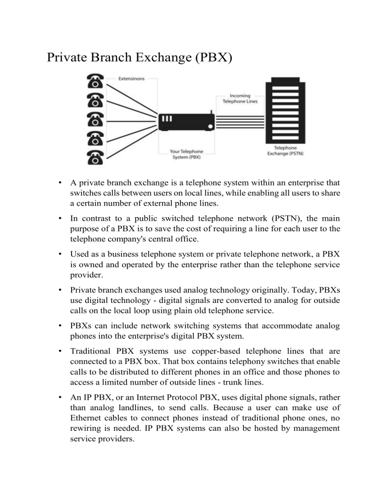
Private Branch Exchange (PBX) • A private branch exchange is a telephone system within an enterprise that switches calls between users on local lines, while enabling all users to share a certain number of external phone lines. • In contrast to a public switched telephone network (PSTN), the main purpose of a PBX is to save the cost of requiring a line for each user to the telephone company's central office. • Used as a business telephone system or private telephone network, a PBX is owned and operated by the enterprise rather than the telephone service provider. • Private branch exchanges used analog technology originally. Today, PBXs use digital technology - digital signals are converted to analog for outside calls on the local loop using plain old telephone service. • PBXs can include network switching systems that accommodate analog phones into the enterprise's digital PBX system. • Traditional PBX systems use copper-based telephone lines that are connected to a PBX box. That box contains telephony switches that enable calls to be distributed to different phones in an office and those phones to access a limited number of outside lines - trunk lines. • An IP PBX, or an Internet Protocol PBX, uses digital phone signals, rather than analog landlines, to send calls. Because a user can make use of Ethernet cables to connect phones instead of traditional phone ones, no rewiring is needed. IP PBX systems can also be hosted by management service providers. • While hosted systems require monthly fees, there are fewer end-user hardware costs associated with their use. Smaller PBX systems, often referred to as virtual PBXs, offer hosted services but with fewer features. They are more appropriate for small businesses. PBX Traditional PBX IP PBX Cloud based PBX Dual Tone Multiple Frequency (DTMF) • DTMF is a multi-frequency tone dialing system used by the push button keypads in telephone and mobile sets to convey the number or key dialed by the caller. • DTMF has enabled the long distance signaling of dialed numbers in voice frequency range over telephone lines. This has eliminated the need of telecom operator between the caller and the callee and evolved automated dialing in the telephone switching centers. • A DTMF keypad (generator or encoder) generates a sinusoidal tone which is mixture of the row and column frequencies. • The row frequencies are low group frequencies. The column frequencies belong to high group frequencies. • This prevents misinterpretation of the harmonics. Also, the frequencies for DTMF are so chosen that none have a harmonic relationship with the others and that mixing the frequencies would not produce sum or product frequencies that could mimic another valid tone. • The column tones are slightly louder than the row tones to compensate for the high-frequency roll off of voice audio systems. • DTMF tones can represent one of the 16 different states or symbols on the keypad. This is equivalent to 4 bits of data, also known as nibble. Strowger Switch • It is also known as step by step or simply step switch. The first “step” switch was installed in Indiana in 1892. They were popular with independent telephone companies, but installation in AT&T’s Bell System did not start until 1911. • The step-by-step switch is conveniently based on a stepping relay of 10 levels. In its simplest form, which uses direct progressive control, dial pulses from a subscriber’s telephone activate the switch. • If a subscriber dials a 3, three pulses from the subscriber subset are transmitted to the switch. The switch then steps to level 3 in the first relay bank. The second relay bank is now connected waiting for the second dialed digit. It accepts the second digit from the subscriber and steps to its equivalent position and connects to the third relay bank and so on for four or seven dialed digits. Assume that a certain exchange only serves three-digit numbers. A dialed number happens to be 375 and will be stepped through three sets of banks of 10 steps each. Crossbar Switch • The crossbar is actually a matrix switch used to establish the speech path. • An electrical contact is made by actuating a horizontal and vertical relay. • To make contact at point B4 on the matrix, horizontal relay B and vertical relay 4 must close to establish the connection. • Such closing is usually momentary, but sufficient to cause latching. • Two forms of latching are found in crossbar practice: mechanical and electrical. • The latch keeps the speech path connection until an “on-hook” condition occurs. • Once the latching occurs, connection B4 is “busied out,” and the horizontal and vertical relays are freed-up to make other connections for other calls. Transmission of Telephone Signals To transport electrical signals, a transmission medium is required. There are four types of transmission media: 1. Wire pair 2. Coaxial cable 3. Fiber-optic cable 4. Radio Wire pair • A wire pair consists of two wires that commonly use a copper conductor, although aluminum conductors have been employed. • A basic impairment of wire pair is loss. Loss is synonymous with attenuation. Loss can be defined as the dissipation of signal strength as a signal travels along a wire pair, or any other transmission medium for that matter. Loss or attenuation is usually expressed in decibels (dB). • Loss causes the signal power to be dissipated as a signal passes along a wire pair. Power is expressed in watts. For this application, the use of milliwatts may be more practical. If we denominate loss with the notation LdB, 𝑃1 𝐿𝑑𝐵 = 10 log 𝑃2 • where P1 is the power of the signal where it enters the wire pair, and P 2 is the power level of the signal at the distant end of the wire pair. • Wire-pair transmission suffers other impairments besides loss. One of these impairments is crosstalk. • Most of us have heard crosstalk on our telephone line. It appears as another, “foreign” conversation having nothing to do with our telephone call. • One basic cause of crosstalk is from other wire pairs sharing the same cable as our line. These other conversations are electrically induced into our line. To mitigate this impairment, physical twists are placed on each wire pair in the cable. Generally there are 2 to 12 twists per foot of wire pair. From this we get the term twisted pair. • Another impairment causes a form of delay distortion on the line, which is cumulative and varies directly with the length of the line as well as with the construction of the wire itself. • It has little effect on voice transmission but can place definition restrictions on data rate for digital/data transmission on the pair. The impairment is due to the capacitance between one wire and the other of the pair, between each wire and ground, and between each wire and the shield, if a shield is employed. Coaxial Cables • The conducting pair consists of a cylindrical tube with a single wire conductor going down its center. • In practice the center conductor is held in place accurately by a surrounding insulating material that may take the form of a solid core, discs, or beads strung along the axis of the wire or a spirally wrapped string. • From about 1953 to 1986, coaxial cable was widely deployed for longdistance, multichannel transmission. Its frequency response was exponential. Thus, its loss increased drastically as frequency was increased. Radio Transmission Radio transmission is based on radiated emission. The essential elements of any radio system are: (1) A transmitter for generating and modulating a “high-frequency” carrier wave with an information baseband, (2) A transmitting antenna that will radiate the maximum amount of signal energy of the modulated carrier in the desired direction, (3) A receiving antenna that will intercept the maximum amount of the radiated energy after its transmission through space, and (4) A receiver to select the desired carrier wave, amplify the signal, detect it, or separate the signal from the carrier. Switching Techniques • For transferring the message from the sender to the receiver we use various message switching techniques. • The technique we use, depends upon the factors like kind of message we want to transfer, quality of the message, etc. • There are three types of message switching techniques used: 1. Circuit Switching 2. Message Switching 3. Packet Switching Circuit Switching • Circuit Switching is a switching technique method that establishes a dedicated path between the sender and the receiver to send the data. The example of a circuit-switch network is a telephone network. • A communication through circuit switching has 3 phases: 1. Circuit Establishment: In the first phase, a dedicated link is established between the sender and the receiver through a number of switching centers or nodes. 2. Data Transmission: Once the connection is established data is transferred from the sender to the receiver over the connection established. This connection remains as long as the data transfer takes place. 3. Circuit Disconnect: Once the data transfer is completed the circuit disconnects. The disconnection is initiated by one of the user i.e the sender or the receiver. • Suppose we want to send the data from the A to B, we will first have to establish the connection in the switching nodes. These nodes establish a link such that there is a dedicate path from A to B. When the link is established the date is transferred. Once the data sharing takes place, the links are broken and are free to be used by some other systems. • Advantages of Circuit Switching Network 1. Once the circuit is established there is no delay in data transfer. So it is useful in real-time data transfer like voice calls. 2. The communication channel is dedicated which ensures a steady rate of data transfer. 3. There is no need of packet sorting in the receiver's side because all the node follow the same path and in the same order • Disadvantages of Circuit Switching Network 1. As the channel is dedicated it cannot be used to transfer any other data even if the connected systems are not using the channel. Hence circuit switching is insufficient in terms of resource utilization. 2. It is expensive as compared to other techniques because of dedicated path requirements. 3. The time required to establish the connection between the source and destination is high. This means that there is no communication until the connection is established and the resources are available. 4. It mainly used in voice traffic so not suitable for data transmission. Message Switching • Message switching is a connectionless network in which the data from the source to destination is sent in the form of message units. A message is a logical unit of the information that can be of any length. The sender and the receiver are not directly connected. There are many intermediate nodes which ensure the delivery of the message to the destination. The message switching was used in sending telegrams. • It has two main characteristics: 1. Store and Forward: The sender sends the messages to the nodes. The intermediate nodes store the complete message temporarily. The node inspects for any error and then transfers to the next node on the basis available free channel. Then the data of that node will be forwarded or transfered to the next node only if the next node has sufficient resources. The actual path taken by the message is dynamic as the path is established as it travels. 2. Message Delivery: Each message must have a header that contains the routing information like source and destination address. All these pieces of information are wrapped in the message and then the message is sent from the source to destination. • Suppose we have to send two messages i.e Message 1 and Message 2 from the sender to the receiver. We will directly send the message without establishing any connection. • Advantages of Message Switching Network 1. The efficiency is improved as a single channel can now be used for transferring many messages. 2. The source and the destination don't need to be ready at the same time. Even if the receiver is not ready the sender can send the message and it can be stored by the nodes temporarily. 3. The transfer of message is possible also when the transfer rate of the sender and receiver is different. 4. It reduces congestion due to its store and forward property. Any node can be used to store the message until the next resources are available to transfer the data. • Disadvantages of Message Switching Network 1. The store and forward method cause delay at each node. So, the primary disadvantage of message switching is that it cannot be used for real-time applications like voice or video calls. 2. As the message can be of any length so each node must have sufficient buffer to store the message. Packet Switching • Packet switching is a message switching technique in which the data is divided into packets. These packets contain a header that contains the information of the destination. The packets find the route with the help of this information. • A packet contains header and payload. The header contains the routing information and the payload contains the data to be transferred. • The packet switching is also based on the Store and Forward method. Each packet contains the source and destination information so, they can independently travel in the network. The packet belonging to the same file may take different paths depending upon the availability of the path. • At the destination, these packets are re-assembled. It the responsibility of the receiver to re-arrange the received packet to the original data. • Suppose the data to be sent is divided into three packets i.e. 1, 2, 3. Now, these packets travel independently in the network. The intermediate nodes forward the nodes according to the availability of the channel. At the receiver side, the order of packets can be different. It is the duty of the receiver to re-arrange the received packets. • Advantages of Message Switching Network 1. Packets have fixed sizes, so the switching devices do not require large secondary storage devices. The storage was a problem in message switching which is removed here. 2. It is more efficient for data transmission as it doesn't require any dedicated paths. 3. If the link is busy or not available, the packets can be re-routed. This ensures a reliable connection. 4. The same channel can be used by many users simultaneously. 5. With improved protocols, packet switching is used for applications like Skype, WhatsApp, etc. Disadvantages of Message Switching Network 1. They cannot be used for applications that cannot afford delays like highquality voice calls. 2. Protocols used in packet-switching are complex and require higher implementation costs. 3. If the network is overloaded then the packets may be lost or delayed. This may lead to loss of critical information. 4. Sorting of received packets is required at the receiver's side. Telegraph • In a basic telegraph system, there is a battery terminal connected to a copper wire looping it back to the other electrode. • A buzzer or other sound-generating device is inserted into that loop at the farthest end of the wire before looping back • The loop has a certain resistance, which is a function of its length and the diameter of the wire. • The longer we make the loop, the greater the resistance. As the length increases, the current in the loop decreases. There will be some point where the current is so low that the buzzer will not work. • The maximum loop length can be increased by using wire with a greater diameter or by using electrical repeaters placed near the maximum length point. • Another relay technique involved a human operator. At the far end of the loop an operator copied the message and retransmitted it down the next leg of the circuit. • At the near end, which we may call the transmitting end, there is an electrical switch, which we will call a key. • The key consists of two electrical contacts, which, when pressed together, make contact, thereby closing the circuit and permitting current to flow. The key is spring-loaded, which keeps it normally in the open position (no current flow). • To convey encrypted message, the written word, a code was developed by Morse, consisting of three elements: a dot, where the key was held down for a very short period of time; a dash, where the key was held down for a longer period of time; and a space, where the key was left in the “up” position and no current flowed. • By adjusting the period of time of spaces, the receiving operator could discern the separation of characters and separation of words, where the space interval was longer Practical Telegraph • A more practical telegraph system is shown in figure. It has just one metallic wire connecting the west station to the east station. The second wire is replaced with ground. The earth is a good conductor, and so we use earth, called ground, as the second conductor (or wire). Such a telegraph system is called single-wire ground return. • In this case, when both keys are closed, a DC circuit is traced from a battery in the west station through the key and relay at that point to the line wire, and from there it is traced through the relay and key at the east station and back through the earth (ground) to the battery. The relays at each end, in turn, control the local circuits, which include a separate battery and a sounder. • Opening and closing the key at one end, while the key at the other end is closed, causes both sounders to operate accordingly. • A relay is a switch that is controlled electrically. It consists of (a) wire wrapped around an iron core and (b) a hinged metal strip, which is normally open. • When current flows through the windings, a magnetic field is set up, thereby drawing the hinged metal strip into a closed position and causing current to flow in the secondary circuit. • It is a simple open-and-closed device such that when current flows there is a contact closure (the metal strip) and when there is no current through the windings, the circuit is open. There is a spring on the metal strip, holding it open except when current flows. Integrated Services of Digital Networking (ISDN) • ISDN is a telephone network-based infrastructure that allows the transmission of voice and data simultaneously at a high speed with greater efficiency. • This is a circuit switched telephone network system, which also provides access to Packet switched networks. • ISDN has 3 interfaces: 1. Basic Rate Interface (BRI) 2. Primary Rate Interface (PRI) 3. Broadband-ISDN (B-ISDN) Voice-Over IP (VoIP) • Figure shows a block diagram of VoIP operation from an analog signal deriving from a standard telephone, which is digitized and transmitted over the Internet via a conversion device. • Then, at the distant end, it is converted back to analog telephony using a similar device suitable for input to a standard telephone. The gateway is placed between the voice codec and the digital data transport circuit. • An identical device will also be found at the far end of the link. This equipment carries out the signaling role on a telephone call among other functions. • We have the analog signal deriving from a standard telephone set. The signal is then converted to a digital counterpart using one of seven or so codecs [coder-decoder(s)] that the VoIP system designer has to select from. • The binary output of the codec is then applied to a conversion device (i.e., a “packetizer”) that loads these binary 1s and 0s into an IP payload of from 20 to 40 octets in length. • The output of the converter consists of IP packets that are transmitted on the web or other data circuit for delivery to the distant end. • At the far end the IP packets or frames are input to a converter (i.e., depacketizer) that strips off the IP header, stores the payload, and then releases it in a constant bit stream to a codec (i.e., a D–A converter). This codec must be compatible with its near-end counterpart. The codec converts the digital bit stream back to an analog signal that is then input to a standard telephone subset.

