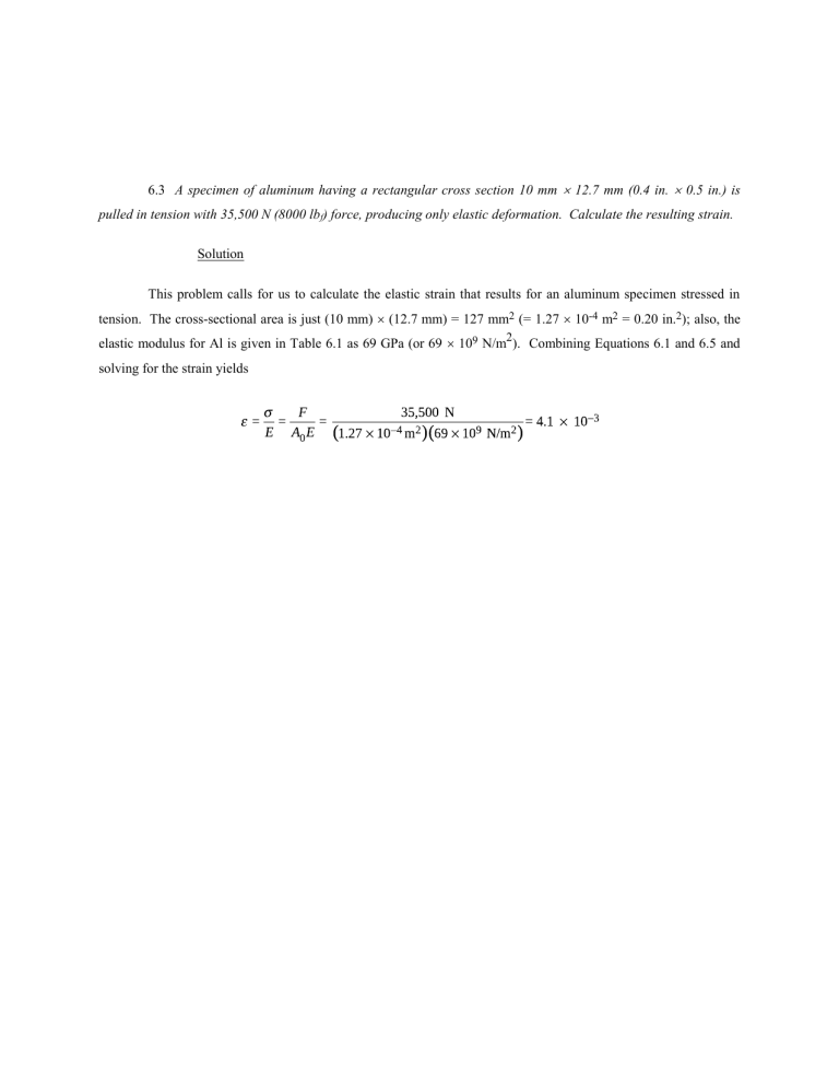
6.3 A specimen of aluminum having a rectangular cross section 10 mm 12.7 mm (0.4 in. 0.5 in.) is pulled in tension with 35,500 N (8000 lbf) force, producing only elastic deformation. Calculate the resulting strain. Solution This problem calls for us to calculate the elastic strain that results for an aluminum specimen stressed in tension. The cross-sectional area is just (10 mm) (12.7 mm) = 127 mm2 (= 1.27 10-4 m2 = 0.20 in.2); also, the 2 elastic modulus for Al is given in Table 6.1 as 69 GPa (or 69 109 N/m ). Combining Equations 6.1 and 6.5 and solving for the strain yields 6.5 A steel bar 100 mm (4.0 in.) long and having a square cross section 20 mm (0.8 in.) on an edge is pulled in tension with a load of 89,000 N (20,000 lb f), and experiences an elongation of 0.10 mm (4.0 10-3 in.). Assuming that the deformation is entirely elastic, calculate the elastic modulus of the steel. Solution This problem asks us to compute the elastic modulus of steel. For a square cross-section, A0 = b0 is the edge length. Combining Equations 6.1, 6.2, and 6.5 and solving for E, leads to = 223 109 N/m2 = 223 GPa (31.3 106 psi) , where 6.7 For a bronze alloy, the stress at which plastic deformation begins is 275 MPa (40,000 psi), and the modulus of elasticity is 115 GPa (16.7 106 psi). (a) What is the maximum load that may be applied to a specimen with a cross-sectional area of 325 mm2 (0.5 in.2) without plastic deformation? (b) If the original specimen length is 115 mm (4.5 in.), what is the maximum length to which it may be stretched without causing plastic deformation? Solution (a) This portion of the problem calls for a determination of the maximum load that can be applied without plastic deformation (Fy). Taking the yield strength to be 275 MPa, and employment of Equation 6.1 leads to = 89,375 N (20,000 lbf) (b) The maximum length to which the sample may be deformed without plastic deformation is determined from Equations 6.2 and 6.5 as 6.17 A cylindrical specimen of some alloy 8 mm (0.31 in.) in diameter is stressed elastically in tension. A force of 15,700 N (3530 lbf) produces a reduction in specimen diameter of 5 10-3 mm (2 10-4 in.). Compute Poisson's ratio for this material if its modulus of elasticity is 140 GPa (20.3 106 psi). Solution This problem asks that we compute Poisson's ratio for the metal alloy. From Equations 6.5 and 6.1 Since the transverse strain x is just and Poisson's ratio is defined by Equation 6.8, then 6.23 A cylindrical rod 100 mm long and having a diameter of 10.0 mm is to be deformed using a tensile load of 27,500 N. It must not experience either plastic deformation or a diameter reduction of more than 7.5 10-3 mm. Of the materials listed as follows, which are possible candidates? Justify your choice(s). Modulus of Elasticity (GPa) Yield Strength (MPa) Poisson’s Ratio Aluminum alloy 70 200 0.33 Brass alloy 101 300 0.34 Steel alloy 207 400 0.30 Titanium alloy 107 650 0.34 Material Solution This problem asks that we assess the four alloys relative to the two criteria presented. The first criterion is that the material not experience plastic deformation when the tensile load of 27,500 N is applied; this means that the stress corresponding to this load not exceed the yield strength of the material. Upon computing the stress Of the alloys listed, the Ti and steel alloys have yield strengths greater than 350 MPa. Relative to the second criterion (i.e., that d be less than 7.5 10-3 mm), it is necessary to calculate the change in diameter ∆d for these three alloys. From Equation 6.8 Now, solving for ∆d from this expression, For the steel alloy Therefore, the steel is a candidate. For the Ti alloy Hence, the titanium alloy is not a candidate. 6.29 A cylindrical specimen of aluminum having a diameter of 0.505 in. (12.8 mm) and a gauge length of 2.000 in. (50.800 mm) is pulled in tension. Use the load–elongation characteristics tabulated below to complete parts (a) through (f). Load Length N lbf mm in. 0 0 50.800 2.000 7330 1650 50.851 2.002 15,100 3,400 50.902 2.004 23,100 5,200 50.952 2.006 30,400 6,850 51.003 2.008 34,400 7,750 51.054 2.010 38,400 8,650 51.308 2.020 41,300 9,300 51.816 2.040 44,800 10,100 52.832 2.080 46,200 10,400 53.848 2.120 47,300 10,650 54.864 2.160 47,500 10,700 55.880 2.200 46,100 10,400 56.896 2.240 44,800 10,100 57.658 2.270 42,600 9,600 58.420 2.300 36,400 8,200 59.182 2.330 Fracture (a) Plot the data as engineering stress versus engineering strain. (b) Compute the modulus of elasticity. (c) Determine the yield strength at a strain offset of 0.002. (d) Determine the tensile strength of this alloy. (e) What is the approximate ductility, in percent elongation? (f) Compute the modulus of resilience. Solution This problem calls for us to make a stress-strain plot for aluminum, given its tensile load-length data, and then to determine some of its mechanical characteristics. (a) The data are plotted below on two plots: the first corresponds to the entire stress-strain curve, while for the second, the curve extends to just beyond the elastic region of deformation. (b) The elastic modulus is the slope in the linear elastic region (Equation 6.10) as (c) For the yield strength, the 0.002 strain offset line is drawn dashed. It intersects the stress-strain curve at approximately 285 MPa (41,000 psi). (d) The tensile strength is approximately 370 MPa (54,000 psi), corresponding to the maximum stress on the complete stress-strain plot. (e) The ductility, in percent elongation, is just the plastic strain at fracture, multiplied by one-hundred. The total fracture strain at fracture is 0.165; subtracting out the elastic strain (which is about 0.005) leaves a plastic strain of 0.160. Thus, the ductility is about 16%EL. (f) From Equation 6.14, the modulus of resilience is just which, using data computed above gives a value of 6.D1 A large tower is to be supported by a series of steel wires. It is estimated that the load on each wire will be 11,100 N (2500 lbf). Determine the minimum required wire diameter assuming a factor of safety of 2 and a yield strength of 1030 MPa (150,000 psi). Solution For this problem the working stress is computed using Equation 6.24 with N = 2, as Since the force is given, the area may be determined from Equation 6.1, and subsequently the original diameter d0 may be calculated as And = 5.23 10-3 m = 5.23 mm (0.206 in.) 6.3FE The following figure shows the tensile stress-strain curve for a plain-carbon steel. (a) What is this alloy’s tensile strength? (A) 650 MPa (C) 570 MPa (B) 300 MPa (D) 3000 MPa (b) What is its modulus of elasticity? (A) 320 GPa (C) 500 GPa (B) 400 GPa (D) 215 GPa (c) What is the yield strength? (A) 550 MPa (C) 600 MPa (B) 420 MPa (D) 1000 MPa Solution (a) The tensile strength (the maximum on the curve) is approximately 570 MPa. Therefore, C is the correct answer. (b) The elastic modulus is just the slope of the initial linear portion of the curve, which may be determined using Equation 6.10: If we take and to be zero and = 300 MPa, then its corresponding strain (from the inset) is about 0.0014. Thus, we calculate the modulus of elasticity as follows: Thus, D is the correct answer. (c) The 0.002 strain offset line intersects the stress-strain curve at approximately 550 MPa, which means that the correct answer is A.

