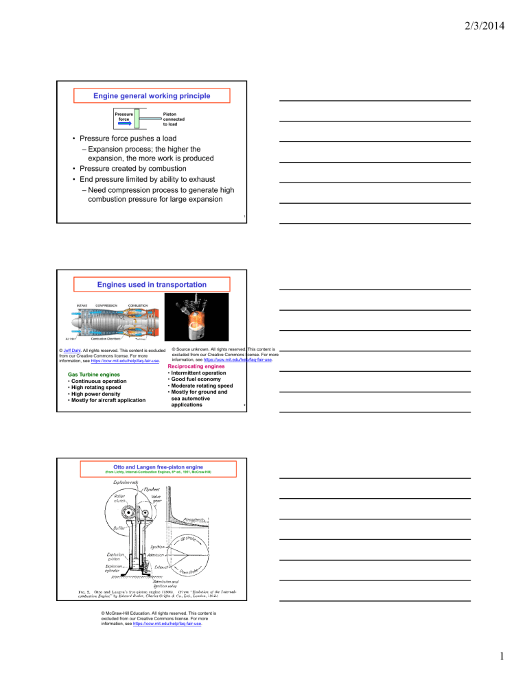
2/3/2014 Engine general working principle Pressure force Piston connected to load • Pressure force pushes a load – Expansion process; the higher the expansion, the more work is produced • Pressure created by combustion • End pressure limited by ability to exhaust – Need compression process to generate high combustion pressure for large expansion 1 Engines used in transportation © Jeff Dahl. All rights reserved. This content is excluded from our Creative Commons license. For more information, see https://ocw.mit.edu/help/faq-fair-use. Gas Turbine engines • Continuous operation • High rotating speed • High power density • Mostly for aircraft application © Source unknown. All rights reserved. This content is excluded from our Creative Commons license. For more information, see https://ocw.mit.edu/help/faq-fair-use. Reciprocating engines • Intermittent operation • Good fuel economy • Moderate rotating speed • Mostly for ground and sea automotive applications 2 Otto and Langen free-piston engine (from Lichty, Internal-Combustion Engines, 6th ed., 1951, McCraw-Hill) © McGraw-Hill Education. All rights reserved. This content is excluded from our Creative Commons license. For more information, see https://ocw.mit.edu/help/faq-fair-use. 1 Notes: Lecture 1: Introduction to ICE Vocabulary Engine: Device to convert fuel energy to mechanical energy ― Fuel energy to thermal energy by combustion ― Thermal energy to mechanical energy by expansion Internal combustion: combustion takes place in working fluid External combustion: combustion occurs externally; energy coupled to working fluid by heat transfer device Open cycle: working fluid discharged to atmosphere; e.g. all ICE Close cycle: working fluid recycled through engine; e.g. steam engine with condenser ICE Size: displacement volume 1cc to 1m3 per cylinder; comment on why it is difficult to build engine outside this range. Power: 10 W to 108 W per cylinder Applications: Automotive, marine, power generation, mechanical devices Classification: ― by application: Car, Truck, Marine, Rail, Stationary generation, … ― by basic engine design: reciprocating, rotary, in-line block, V-block, radial, oppose piston, pre-/open chamber ― by working cycle: 2-stroke, 4-stroke, naturally aspirated , turbo-charged, super-charged, turbo-compound ― by fuel: gasoline, diesel, alcohol, natural gas, … ― by mixture preparation: carbureted, fuel injection ― by ignition: spark ignited, compression ignited History Circa 1860 Event Rudimentary ICE 1867 Atmospheric free piston engine 1876 1878 1892 4-stroke engine 2-stroke engine Compression Ignition 4-stroke People and key concept Jean J. Lenoir. ― Key concept: Combustion increases temperature and gas expands. Expanding gas drives piston to produce mechanical energy. ― Modified steam energy; no compression ― Operated at 10 cycles/min; efficiency <5% because of low effective compression ratio Sold 500 of them Nicolaus Otto and Eugene Langen ― Key concept: still no compression, but use the inertia of a heavy piston to over-expand the combustion gas to below atmosphere, thereby increasing the expansion ratio. Output mechanical work stored as gravitational potential energy in heavy piston first, and then extracted by clutching piston to fly wheel on downward stroke. ― Larger expansion ratio: efficiency increased to 11% ― Operate at 28 cycles/minute ― Used a flame ignitor through a sliding window Sold 5000, dominated market for 10 years until introduction of the 4-stroke engine Nicolaus Otto Dougald Clerk Rudolf Diesel ― Key concepts: prevent the very rapid and high pressure heat 2 process via introducing fuel late in the cycle; compression ignition ― Concept developed by the company MAN ― Diesel was in heavy debt, and jumped off a ship. 1870’s 1900’s 1920’s 1920’s 19201960 1960’s 1970’s 1980’s 1980’s 1990’s 2000’s Development of the Petroleum Industry Spark plug dominated the market of ignition devices ICE dominated the market of automotive power plant Tetra-ethyl lead as anti-knock agent Spark plug was invented by Edmond Berger in 1839. Albert Champion was the most successful manufacturer. Main reason for not using the steam engine for vehicles was that too much water was needed. Thomas Midgley, under the direction of Carles Kettering at GM found the compound to suppress knock after extensive search. With leaded gasoline, maximum compression ratio was raised from 5 to 9, and engine efficiency increased substantially Steady development Vehicle emissions became an issue Oil embargo; energy crisis Start of global competition Catalytic converter and unleaded gasoline Smog mechanism was discovered by Haagen Smit The 3 way catalyst reduced emissions of CO, HC and NOx by more than an order of magnitude, and was the enabler for the vehicles to meet emissions regulations Recognition of importance of green house gas Towards sustainable transportation Gas exchange process of 4- and 2-stroke engines See figures 1-2 and 1-3. ― 2-stroke engine theoretically has twice the power density of 2-stroke engine; in practice, the ratio is about 1.4 (value larger for low speed turbo-charger engines) because of incompleteness of scavenging. ― For effective scavenging of the 2-stroke, there will be excess air in the exhaust, and the 3-way catalyst would not work. Therefore 2-stroke SI engine would not be able to meet the stringent emission regulations Engine pressure traces See Fig. 1.8 and 1.15 for SI and Compression Ignition engines ― Pressure measurement is an important diagnostic because it is directly related to the mechanical energy output of the engine (Torque = P dV/d, where is the crank angle); furthermore, interpretation of pressure is unambiguous since it is uniform in the cylinder (except in knocking), whereas temperature is not. ― Empirically for most efficient operation, peak pressure for SI engine is at 14-17o CA-ATC; for diesel is at 7-10o CA-ATC. ― The very rapid pressure rise in the beginning of diesel combustion is the cause of the diesel noise. 3 MIT OpenCourseWare https://ocw.mit.edu 2.61 Internal Combustion Engines Spring 2017 For information about citing these materials or our Terms of Use, visit: https://ocw.mit.edu/terms.


