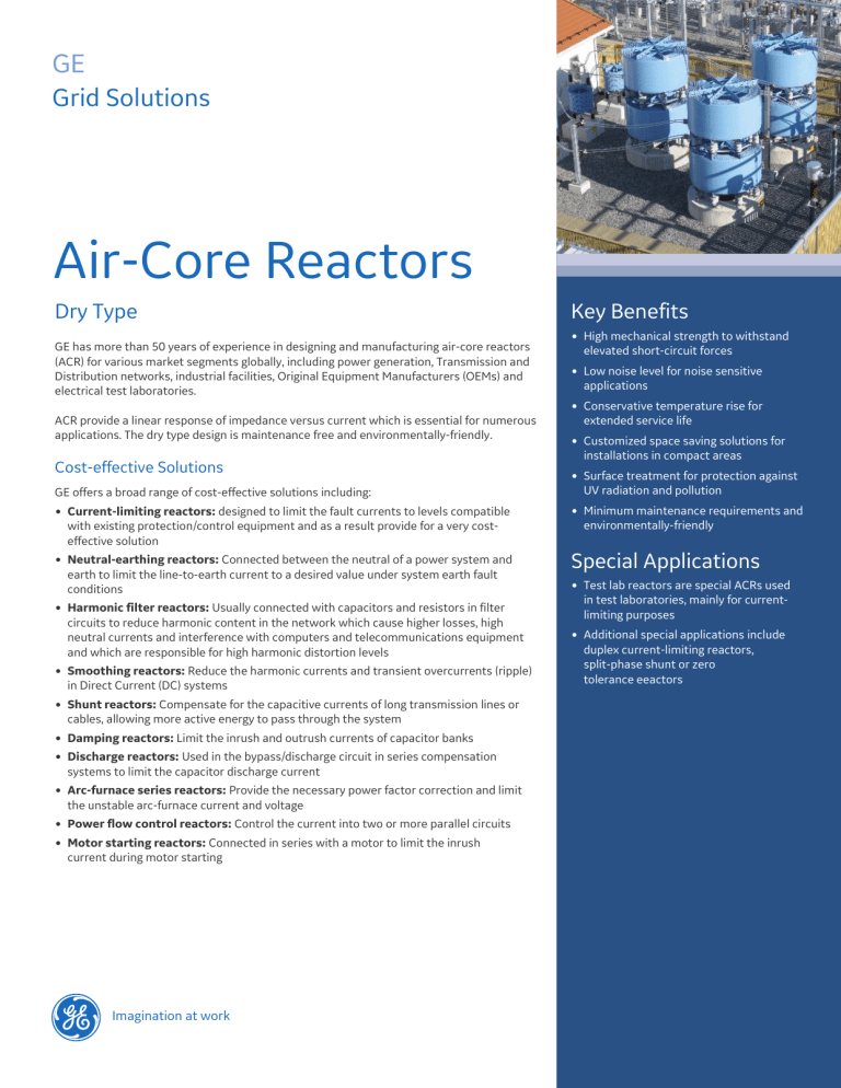
GE Grid Solutions Air-Core Reactors Dry Type GE has more than 50 years of experience in designing and manufacturing air-core reactors (ACR) for various market segments globally, including power generation, Transmission and Distribution networks, industrial facilities, Original Equipment Manufacturers (OEMs) and electrical test laboratories. ACR provide a linear response of impedance versus current which is essential for numerous applications. The dry type design is maintenance free and environmentally-friendly. Cost-effective Solutions GE offers a broad range of cost-effective solutions including: Current-limiting reactors: designed to limit the fault currents to levels compatible with existing protection/control equipment and as a result provide for a very costeffective solution Neutral-earthing reactors: Connected between the neutral of a power system and earth to limit the line-to-earth current to a desired value under system earth fault conditions Harmonic filter reactors: Usually connected with capacitors and resistors in filter circuits to reduce harmonic content in the network which cause higher losses, high neutral currents and interference with computers and telecommunications equipment and which are responsible for high harmonic distortion levels Smoothing reactors: Reduce the harmonic currents and transient overcurrents (ripple) in Direct Current (DC) systems Shunt reactors: Compensate for the capacitive currents of long transmission lines or cables, allowing more active energy to pass through the system Damping reactors: Limit the inrush and outrush currents of capacitor banks Discharge reactors: Used in the bypass/discharge circuit in series compensation systems to limit the capacitor discharge current Arc-furnace series reactors: Provide the necessary power factor correction and limit the unstable arc-furnace current and voltage Power flow control reactors: Control the current into two or more parallel circuits Motor starting reactors: Connected in series with a motor to limit the inrush current during motor starting . Imagination at work Key Benefits High mechanical strength to withstand elevated short-circuit forces Low noise level for noise sensitive applications Conservative temperature rise for extended service life Customized space saving solutions for installations in compact areas Surface treatment for protection against UV radiation and pollution Minimum maintenance requirements and environmentally-friendly Special Applications Test lab reactors are special ACRs used in test laboratories, mainly for currentlimiting purposes Additional special applications include duplex current-limiting reactors, split-phase shunt or zero tolerance eeactors Air Core Reactors Dry Type Inducing Energy with Success Air Core Reactor Applications 1.1. Current Limiting This reactor is series connected to the transmission line or to the feeder to limit the current under system fault conditions to levels compatible with the protection equipment of the circuit. It is a very cost-effective solution, eliminating the need to upgrade the entire switching and protection system when the short-circuit power of the system is increased. This reactor is designed to provide specified impedance and to withstand the rated and fault (short-time) currents during a specified period of time. 1.1 Current-limiting reactor with seismic design 1.1 Current-limiting reactors 1.2. Neutral-Earthing This single-phase reactor is used to ground the neutral point of 3-phase networks to limit the current in the event of a fault between phase and ground. If the circuit is perfectly balanced, the resulting current flow through the reactor will be zero and there will be no losses. 1.3. Smoothing Smoothing reactors are used to reduce the harmonic currents and transient overcurrents in the DC system. They are used in High Voltage Direct Current (HVDC) links and industrial applications such as rectifiers, traction systems, etc. 1.2 Neutral-earthing reactor 1.3 Smoothing reactor 1.4. Harmonic Filtering The harmonic currents are distortions introduced to the network as a result of the operation of power electronics devices, large inductive machines, etc. These harmonic currents create several network problems, such as: Greater losses Malfunctioning control systems High neutral currents Interference with computers Interference with telecommunications equipment. 1.4 High Voltage harmonic filter 1.4 Filter reactor 2 GEGridSolutions.com Air Core Reactors Dry Type 1.5 Shunt Application 1.5.1 Static Var Compensation (SVC) System 1.5.1 Thyristor Controlled Reactors (TCR) reactor Most utilities impose high fees when a certain Harmonic Distortion Level (HDL) threshold is reached. 1.5. Shunt SVC systems provide dynamic power compensation for utilities and industry networks. The main benefits include: dynamic voltage support, improvement of system stability, power oscillation damping, reactive power balancing, flicker control and reduction of losses. An SVC normally consists of a combination of: Thyristor-Controlled Reactors (TCR), Thyristor-Switched Capacitors and Reactors (TSC and TSR), MechanicallySwitched Capacitor banks and Harmonic Filters (HF). Harmonic filter reactors, in association with capacitor units and occasionally resistors, create a filter circuit tuned to a certain frequency (resonance frequency) so as to reduce, block or provide a low impedance path for the harmonic currents in the audio frequency range. They are connected either in a parallel or in a series configuration. Harmonic filters are typically installed in substations, in Static VAr Compensators (SVCs ) and in HVDC links. The reactors are designed to meet specific design criteria such as quality-factor, tolerance of the inductance between phases and of the reactor itself. Special low Q-factor requirements can be met using an integrated damping circuit. 1.5 Shunt Reactor connected to tertiary of HV transformer These reactors are used in a parallel configuration to compensate for the capacitive currents of long transmission lines or cables. As a result, they allow the flow of more active energy through the system. In a low-load situation, shunt reactors may be used to reduce the voltage rise due to capacitance of the transmission line and, in so doing, reduce corona losses. In many installations, the reactors are connected to the tertiary winding of the high voltage transformer. 1.5.1. Static VAr Compensation (SVC) SVC applications are used to provide dynamic voltage stabilisation, improve synchronous stability and operate as steady-state voltage support. The SVC can also be required for dynamic load balancing in industrial installations using large electrical motors and other equipment with variable loads. Typical applications include steel works (steel mills, cranes, arc-furnaces), paper mills, mining companies, etc. 1.5.1 Thyristor Controlled Reactors GEGridSolutions.com 1.6. Damping Reactor This reactor is series connected with one or more capacitor banks to limit the inrush currents that occur during their switching operation. It is designed to offer a specified impedance and to withstand the rated current and the fault current in the event of a short-circuit associated with a high frequency discharge current of the capacitor bank. 1.6 Damping Reactors 3 Air Core Reactors Dry Type 1.7. Discharge Reactor This application includes reactors for series compensation systems which use capacitor banks which are series connected to the transmission lines. Discharge reactors: improve voltage regulation improve system transient stability increase transmission line capacity reduce electrical losses and save on costs. 1.8. Arc-Furnace Series Reactors The arc-furnace series reactor is connected in series with the electrodes of an arc-furnace used to smelt metals (iron, steel, aluminum, etc.). It provides the necessary power factor correction and limits the very unstable arc-furnace current and voltage (flicker), especially during the melting process. Its winding has a high mechanical strength to withstand the forces caused by the fast switching operations of the electrical arc and the high harmonic currents which are inherent to the electrical arc. 1.9. Power Flow Control These reactors are connected in series in a power system (usually a transmission line) to optimize the power flow through modification of the transfer impedance. They change the line impedance characteristic in such a way that the load flow can be controlled, ensuring maximum power transfer over adjacent transmission lines. 2.0. Motor Starting The reactor is series connected with a motor to limit the inrush current during the motor starting operation. After start-up, the reactor is typically bypassed to limit losses in continuous operation. The reactor can be dimensioned to be short-circuit-proof or not. 2.1 Test Laboratory Reactors Test laboratories often require versatile reactors with taps to adjust the inductance value as well as flexible links to connect the reactor in parallel or in series according to test requirements. Usually, the rated current value is low, and the BIL or the short-time current is high. 2.1 Special Reactor for Laboratories 4 GEGridSolutions.com 1.8 Arc-Furnace Reactor Air Core Reactors Dry Type 2.2 Duplex Current-Limiting Reactors 2.3 Split-Phase Shunt Reactors Duplex current-limiting reactors produce a low reactance under normal conditions and high reactance under fault conditions, with the advantage of a low voltage drop under normal conditions. This type of reactor can be used in systems which always remain isolated. Depending on the required ratings, shunt reactors can be manufactured with split-phase design to provide sufficient sensitivity in detecting turn-to-turn faults. In this case, unbalanced currents between two windings of the reactor can be informed for settings of the protection relays. Duplex Reactor 2.2 Duplex Reactor The duplex reactor is designed in such a way that, under normal conditions, the magnetic fields of the two half-coils are opposed, resulting in a low reactance between power supply and load. In case of a fault in one feeding circuit, the fault current flows only through one half-coil, and consequently the opposite flux of the other half-coil is limited by the increased reactance of the half-coil in series with the feeder under fault conditions. 2.3 Split-phase Reactor 2.4 Zero Tolerance Reactors It is possible to use a split-phase arrangement (two vertically installed part coils) if the inductance tolerance requirement is 0 (zero). The inductance is set at nominal value by adjusting the spacing of the part coils. Air Core Reactor Design GE’s reactor windings consist of numerous aluminum or copper conductors connected in parallel. These conductors can be insulated single wires, insulated cables or aluminum profiles separated by fiberglass spacers. The cost-effective solution to be selected, in terms of dimensions and conductor type to be used in each design, depends on the required ratings for the equipment. For encapsulated design, the conductors are mechanically immobilized and encapsulated by epoxy impregnated fiberglass filaments forming cylinders. Depending on the reactor ratings, one or more of these cylinders are connected in parallel between aluminum or copper spiders. The individual cylinders are separated by fiberglass spacers forming cooling ducts. GE has an experienced team of reactive power compensation specialists able to provide customized solutions to meet special customer needs GEGridSolutions.com 5 Air Core Reactors Dry Type Accessories 3.1. Corona Rings When it is necessary to eliminate visible corona, GE reactors are provided with corona rings made from aluminum tubes. 3.2. Bird Barriers On request, GE can provide the reactors with bird barriers. The bird barriers consist of a temperature and UV resistant fiberglass reinforced plastic grid with square-shaped openings. The bird barrier does not adversely affect the cooling of the reactor. 3.3. Insulators GE can provide all the necessary support insulators for the reactors. 3.4. Pedestals The pedestals provided with GE's reactors maintain the magnetic and electrical clearances required by the reactor design to minimize induced losses. 3.5. Enclosures On request, GE can design and supply reactors with enclosures. 3.6. Tapping Reactors can be supplied with tapings for presetable inductance. Air-core Reactor Construction 1 - Lifting lug 2 - Spacers (cooling ducts) 3 - Crossarms (spider) 4 - Terminal 5 - Insulator 6 - Extension brackets (pedestals) 6 GEGridSolutions.com Air Core Reactors Dry Type 5. Terminal Orientation and Hole Patterns Cost-effective solutions Installation 4.1. Location GE's reactors are suitable for either indoor or outdoor installation. Reactors are often installed in existing substations or installed to replace existing reactors. The reactors are designed to fit within space limitations or to be mounted directly onto the existing foundations. They are also designed for use inside enclosures. In this case, the reactors are designed to avoid excessive heating. GE's reactors are supplied with NEMA or IEC flat pad aluminum or copper terminals. Other standards can be supplied on request. Figures 4 & 5 show typical terminal orientations and hole patterns. Other terminal orientations and hole patterns can be provided on request. For copper connectors, bimetallic tin-plated interfaces can be provided. 4.2. Mounting Arrangement Reactors can be mounted individually as single-phase units, sideby-side, or as 3-phase stacks, one coil on top of the other. Special mounting arrangements can also be provided in case of space limitations. Figure 2 below illustrates the options available. Terminal orientation 6. Painting After the curing process, the reactor is carefully prepared before painting with a high-grade quality enamel, which provides longterm protection against UV radiation. The typical colors are Munsell N6.5 grey, ANSI 70, RAL 7037 and RAL 5024, but other colors can be accommodated on request. In heavily polluted environments, GE uses a special painting process (RTV) and reactors can be provided with a top cover to limit the adverse effects of pollution. Mounting arrangements 4.3. Magnetic clearances GE's magnetic-free field plot is available on request. Hole patterns GEGridSolutions.com 7 Formulae Some useful formulae: XL Inductive reactance () f Frequency (Hz) L Rated inductance (H) QL Rated power (VAr) In Rated current (a) Q Quality-factor (Q-factor) Rac Effective resistance () at system or tuning frequency Inquiry Data XL = 2 . . f . L QL = In2 . XL Q = XL Rac Losses = QL Q Quality Control GE has a continuous quality improvement system based on the constant quest for optimized product design, procurement of materials and components, production and customer service. Products assembled by an experienced and well-trained workforce guarantee maximum customer satisfaction. Thanks to this fundamental principle, associated with a formal quality management system, all GE's manufacturing units are ISO 9001, ISO 14001 and OHSAS 18001 certified. Testing The reactor test program is carried out using measurement systems specifically developed for the purpose. Tests comply with international standards such as IEC, ANSI or equivalents. Numerous type tests have been successfully performed on Grid Solutions reactors at recognised laboratories such as KEMA (Holland), CESI (Italy), IREQ (Canada), CEPEL (Brazil) and LAPEM (Mexico). Type test reports are available on request. Rated inductance (mH) or impedance (W) Rated current (A) Harmonic currents (A) System voltage (kV) BIL (kVp) Rated frequency (Hz) Thermal short-time current (kArms)/ duration (s) Mechanical short-time current (kAp) Mounting arrangement Rated power (MVAr): for shunt reactors Additional information: seismic conditions, wind load, pollution level, salt spray, space limitations, operating altitude, compliance standard, ambient temperature, humidity, ice load, duty cycle, tapping requirements, noise requirements, etc. R&D Activities GE's is at the forefront of innovation. The company boasts an international team of research and development experts with many years of experience in the leading-edge technologies emanating from preceding companies. Its aim is to develop innovative, advanced technologies that best meet the market’s needs at an affordable cost while respecting the environment. GE's R&D community works with a dedicated team focusing on reactive power compensation and harmonic filtering. One of its key ambitions is continued leadership in manufacturing ACR solutions. GEGridSolutions.com For more information please contact GE Energy Connections Grid Solutions IEC is a registered trademark of Commission Electrotechnique Internationale. IEEE is a registered trademark of the Institute of Electrical Electronics Engineers, Inc. Worldwide Contact Center GE reserves the right to make changes to specifications of products described at any time without notice and without obligation to notify any person of such changes. Web: www.GEGridSolutions.com/contact Phone: +44 (0) 1785 250 070 Imagination at work GE and the GE monogram are trademarks of General Electric Company. Grid-PEA-L3-ACR-0584-2017_04-EN. © Copyright 2017, General Electric Company. All rights reserved.


