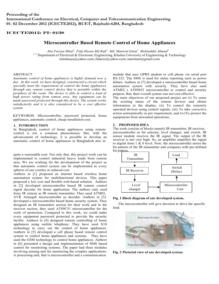
Proceeding of the International Conference on Electrical, Computer and Telecommunication Engineering 01- 02 December 2012 (ICECTE2012), RUET, Rajshahi-6204, Bangladesh ICECTE2012: PI- 0138 Microcontroller Based Remote Control of Home Appliances 1, 2 Abu Farzan Mitul1, Fida Hasan Md Rafi1, Md. Manirul Islam1, Mohiuddin Ahmad1 Department of Electrical & Electronic Engineering, Khulna University of Engineering & Technology mitulnaya@yahoo.com, fidaeee@yahoo.com, mmislam@gmail.com ABSTRACT Automatic control of home appliances is highly demand now a day .In this work, we have designed, constructed a circuit which specially meet the requirement of control the home appliances through any remote control device that is portable within the periphery of the room. The device is able to control a load of high power rating from remote area. Any equipment can be made password protected through this device. The system works satisfactorily and it is also considered to be a cost effective system. KEYWORDS: Microcontroller, password protected, home appliances, automatic control, cheap installation cost. 1. INTRODUCTION In Bangladesh, control of home appliances using remote control is not a common phenomenon. But, with the advancement of technology, it is possible to develop an automatic control of home appliances in Bangladesh also in quite a reasonable cost. Not only that, this project work can be implemented to control industrial heavy loads from remote area. We are working for the development of the project so that automatic control system can be implemented in every spheres of our country at reduced cost. Authors in [1] proposed an internet based wireless home automation system for multifunctional devices. This paper proposed a low cost and flexible web-based solution. Authors in [2] developed microcontroller based IR remote control signal decoder for home application. The authors only used Sony IR remote as IR remote transmitter. They used ATMEL AVR Atmega8 microcontroller as decoder. Authors in [3] developed a microcontroller based home security system. They designed an IR transmitter section for their work and in the receiver section, they used AT89C51 microcontroller for the work of protection. Compared to this work, we could make every equipment password protected to provide the security facility. Authors in [4] designed remote controlling of home appliances using mobile telephony. They have used X10 technology to carry out the control of home appliances. Authors in [5] developed a cell phone based remote control system to control home appliances and systems. They have used the GSM technology to control home appliances. Authors in [6] presented a design and implementation of SMS based control for monitoring systems. The paper had three modules involving sensing unit for monitoring the complex applications. A processing unit, that is microcontroller and a communication module that uses GPRS modem or cell phone via serial port RS-232. The SMS is used for status reporting such as power failure. Authors in [7] developed a microcontroller based home automation system with security. They have also used ATMEL`s AT89S52 microcontroller to control and security purpose. But, their overall system was not cost effective. The main objectives of our proposed project are (i) To sense the existing status of the remote devices and obtain information in the display, (ii) To control the remotely operated devices using control signals, (iii) To take corrective action automatically as per requirement, and (iv)To protect the equipments from unwanted operations. 2. PROPOSED IDEA The work consists of blocks namely IR transmitter, IR receiver, microcontroller as bit selector, level changer, and switch. IR sensor module receives the IR signal. The output of the IR receiver is not very high. So, an amplifier amplifies the signal to digital form 1 & 0 level. Now, the microcontroller stores the bit pattern of the IR transmitter and compares with pre-defined bit pattern. IR Load Transmitter IR Receiver Switch (Relay) Level changer Microcontroller Unit Fig. 1 Block diagram of our developed system. The microcontroller will give decision to drive the specific load. Fig. 2 Pictorial view of our developed system. 3. DESIGN OF HARDWARE 3.1 IR Remote Transmitter In present system, we have used universal TV remote. Every remote has its own protocol. But, one of the biggest advantages of using universal remote controller is that it can learn of brand new remote controllers, which did not exist yet while the universal remote was created. The specialty of our project is that, any remote can be used to drive different loads. But, the condition is bit pattern of the specific remote should be stored in the microcontroller. Microcontroller stores the bit pattern for specific buttons of remote and finally, it just compares with the pre-defined bit pattern to drive the load. We have already taken Sony, Phillips and other remotes in our analysis and in all the cases; we have found quite satisfactory results to drive different loads. The system circuit diagram shown in Fig. 7 has been designed around the ATMEL 89C52 microcontroller [8]. It consists of the arithmetic and the logic unit, I/O Unit, control unit and other various components. Microcontrollers are designed in a single chip, which typically includes a microprocessor, certain byte of R/W memory, from 1K to 2K bytes of ROM, and several signal lines to connect I/O lines. We have used ATMEL 89C52 microcontroller in our project. 3.1.1 Sony SIRC protocol In the project, we have used IR remote switch which uses 12bit SIRC protocol as shown in Fig. 3. The code starts with a header of 2.4ms followed by 7-bit command and 5-bit device address in which least significant bits (LSB) are transmitted first. Then the commands are repeated every 45ms for as long as the key on the remote control is held down. The address and commands exist of logical ones and zeros. A space of 600µs or 1Tand a pulse of 1200 µs or 2T form logical one. A logical zero is formed by a space of 600 µs and a pulse of 600 µs as shown in Fig. 4 [10]. Fig. 3 12-bit SIRC protocol. Fig. 4 IR transmitter protocol (Sony). 3.1.2 Philips RC-5 5 bits is used as address and 6 bit is used as command length. The coding technique of this remote control is Bi-phase coding. Carrier frequency is of 36 KHz. Constant bit time is1.778ms. The typical pulse train of RC-5 message is illustrated in Fig. 5. And the IR transmitter protocol is shown in Fig. 6 [11]. Fig. 5 Pulse train of RC-5 message. Fig. 6 IR transmitter protocol (Phillips). 3.2 Microcontroller as a Bit Selector Fig. 7 Experimental setup of the system. One of the 8051 based microcontrollers is the most popular and widely used chip named as AT89C51. But because of the higher size of ROM as well as RAM needed in our project, we have used AT89C52, which consists of 8KB of ROM and 256 bytes of RAM. The AT89C52 provides the following standard features timer/counter, five vector interrupt architecture with two levels, full duplex serial port, on-chip oscillator and clock circuitry, In addition, the AT89C52 is designed with static logic for operation down to zero frequency and supports two software selectable power saving modes [8]. These features of ATMEL 89C52 make the project a low cost, efficient and reliable. In our project, we have used crystal oscillator of 12 MHz for the proper operation of the device. TSOP-1738 receiver module is used to receive the IR signal from transmitter. When any IR signal is transmitted, microcontroller matches the transmitted bit pattern with the pre-defined bit pattern. In our present system, 12v:0v:12v transformer & IC7805 are used to bias the microcontroller. Thus, it remains connected with the AC mains. 3.3 Switch Microcontroller will give the decision about which load has to be driven depending on the pressed button from remote. Any load of any power rating can be driven using this project. In case of load of high power rating, the relay switch has to be changed. 512 loads of 1 MW, we just changed the relay configurations. So, to drive loads of several MW, the project does not depend on the rating of power. Rather, changes in relay configurations make the project possible to drive loads of any power ratings. A part from these, we have also fixed a display board on the project to provide timer facility for driving different loads. Using this timer facility, we can fix a specific time (say 15 min, 30 min etc.) for which the load will remain on/off. If anyone wants to drive a load at a particular time, then the person can do it using the timer facility through the remote control. In short, load on/off can be made fully time dependent through this project using the remote control. 4. SOFTWARE PART The operation of MCU is written in embedded-C language. In Fig. 8, the basic flow chart of the system software is shown. Start Initialize System Peripheral IR Sensor Acquisition, Decode command Does it match with predefined bit NO YES Return Fig. 8 Flow chart of proposed system. When the device is powered –up, the initialization part of the device software biases various on-chip peripherals such as interrupts, port, timer etc. 6. RESULT AND ANALYSIS 6.1 Proper Decoding IR receiver could decode transmitted IR signal for the operation of microcontroller. Load on/off is tested about 100 times using the remote control. Due to different bit pattern in different buttons make the circuit possible to switch to different loads. 1 1 0.8 0.8 0.6 0.6 bit 5. REAL SYSTEM ANALYSIS This simulation architecture is used for driving several loads using remote control. In our work, as a part of trial, we implemented our project to drive a tube light, fan and multiplug. Using multi-plug, we were able to drive various loads (rated: 230v (50 Hz), 5A). Fig. 10 Microcontroller interfaced with 16×2 LCD. Our project can also protect any equipment to turn on/off instantaneously. If any user wants to make his equipment password protected, then he just needs to ON the password protection option through the display board (LCD). The user can specify any password for his equipment. In this case, other user will not be able to turn ON the equipment without knowing the password. Now, if the user wants to withdraw the password protection option, then he can also do the same. bit Load ON/OFF 0.4 0.4 0.2 0.2 0 0.1 0.2 0.3 0.4 0.5 0.6 0.7 0.8 0.9 1 1.1 0 0.1 0.2 0.3 0.4 0.5 0.6 Time (sec) 0.7 0.8 0.9 1 1.1 Time (sec) Fig. 9 Experimental analysis of the project Meanwhile, we have increased load driving capability from 3 to 8 by changing the program in microcontroller. To drive Fig. 11 Bit pattern of button 1 (left) & 6 ( right). Similar bit pattern simulations for different buttons shows, how microcontroller is able to differentiate the transmitted IR signal to drive different loads. 513 6.2 Life Time The project is able to drive a load without any kind of damage for about 2 years. The performance of the device is quite satisfactory. It is desirable that it can work properly for any kind of loads of any power ratings quite satisfactorily. 6.3 Password Protection The project is tested to verify its protection ability and it is found that, in every case, the microcontroller grants access only for the right password. In case of wrong password, the project does not response. These results have proved password protection ability of our project. 6.4 The Project in Perspective of Bangladesh The cost required for the implementation of the project is estimated. The estimated cost is shown in Table 1. Table 1 Total Cost of the overall project implementation Name of component Number (pieces) Cost in Tk Microcontroller 01 90.00 Crystal oscillator 01 10.00 Remote controller 01 120.00 Transformer 01 90.00 Diode 04 6.00 IR receiver 01 25.00 IC Regulator 01 20.00 Heat sink 01 50.00 Capacitor 03 24.00 Transistor 10 100.00 Relay 08 240.00 R & Variable R 23 23.00 LCD display 01 240.00 PCB and wires 50.00 Total =1115.00 =USD 14 (app.) Fig. 12 Plan of implemetation in a room. In Fig. 12, we can see the design of the work in a room. Our purpose is to take control over every equipments of a room. 7. CONCLUSION In our work, we tried to develop an automatic control system which is not dependent on the power rating if the load. Timer facility of the project provides an extra advantage to the user. Timer facility allows the user to on/off the load for any specific time. Our target is to develop an automatic control system for home appliances where the project will be able to decide to turn off all the loads after leaving the room. In this project, the user can be able to get the security facility. For example, in case of fire in house, the security system will provide an alarm. Not only that, other security facility can also be included in our project. 8. FUTURE WORK In near future, automation will cover every industries and homes for driving different loads and facilitate the livelihood of human being. 9. ACKNOWLEDGEMENTS Special Thanks to Dr. Mohiuddin Ahmad for his supervision on this project. REFERENCES [1] A. Z. Alkar, U. Buhur, "An Internet Based Wireless Home Automation System for Multifunctional Devices," IEEE Consumer Electronics, vol. 51, no. 4, pp. 11691174, 2005. [2] G. S. Nhivekar and R.R.Mudholkar, “Microcontroller Based IR Remote Control Signal Decoder for Home Application”, Advances in Applied Science Research, vol. 2 no. 4, pp. 410-416, 2011. [3] http://www.123eng.com/projects/microcontroller_based_ home_security_project.html, Web. [4] R. Shahriyar, E. Hoque, S. M. Sohan, I. Naim, M. M. Akbar, and M. K. Khan, “Remote Controlling of Home Appliances using Mobile Telephony”, International Journal of Smart Home, Vol. 2, No. 3, July, 2008. [5] C. K. Das, M. Sanaullah, H. M. G. Sarower and M. M. Hassan, “Development of a cell phone based remote control system: an effective switching system for controlling home and office appliances”, International Journal of Electrical & Computer Sciences IJECS, Vol. 9, No. 10, pp. 37-43, 2009. [6] M. S. H. Khiyal, A. Khan, and E. Shehzadi, “SMS Based Wireless Home Appliance Control System (HACS) for Automating Appliances and Security”, Issues in Informing Science and Information Technology, vol. 9, pp. 887-894, 2009. [7] I. Kaur, “Microcontroller Based Home Automation SystemWith Security”, International Journal of Advanced Computer Science and Applications (IJACSA) ,Vol. 1, No. 6, December 2010. [8] www.atmel.com [9] Bergmans S., Oisterwijk, Sony SIRC Protocol [online]. [10] http://www.sbprojects.com/knowledge/ir/rc5.php. 514


