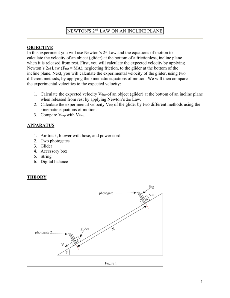
NEWTON'S 2 nd LAW ON AN INCLINE PLANE OBJECTIVE In this experiment you will use Newton’s 2nd Law and the equations of motion to calculate the velocity of an object (glider) at the bottom of a frictionless, incline plane when it is released from rest. First, you will calculate the expected velocity by applying Newton’s 2nd Law (Fnet = MA), neglecting friction, to the glider at the bottom of the incline plane. Next, you will calculate the experimental velocity of the glider, using two different methods, by applying the kinematic equations of motion. We will then compare the experimental velocities to the expected velocity: 1. Calculate the expected velocity Vtheo of an object (glider) at the bottom of an incline plane when released from rest by applying Newton’s 2nd Law. 2. Calculate the experimental velocity Vexp of the glider by two different methods using the kinematic equations of motion. 3. Compare Vexp with Vtheo. APPARATUS 1. 2. 3. 4. 5. 6. Air track, blower with hose, and power cord. Two photogates Glider Accessory box String Digital balance THEORY flag photogate 1 V=0 glider photogate 2 V q Figure 1 1 Method 1 1. Apply N2L to the glider to find the acceleration after released from rest. 2. Derive and expression for the velocity V = V(g, è, x) of the glider at the bottom of the incline plane. g = acceleration of gravity θ = incline angle x = distance traveled by glider Method 2 1. Derive an expression for V = V(x,t) of the glider at the bottom of the incline plane by applying the kinematic equations of motion. x = distance traveled by glider t = time for glider to travel distance X Method 3 1. Use V = d/t to find the velocity of the glider at the bottom of the incline plane. d = diameter of flag on glider ∆t = time for flag to go through photogate at bottom of incline PROCEDURE Method 1 [V = V(g, θ, x)] 1. Set the distance between photogates approximately x ≈ 1m 2. Measure the angle θ as accurately as possible. (DO NOT USE A PROTRACTOR) The angle should be near 150. 3. Calculate V. Call this Vtheo , the expected value of the velocity at bottom of incline plane. Method 2 [V = V(x,t)] 1. Attach the small flag from the accessory box onto the glider. 2. Set the distance between photogates approximately x ≈ 1m. 3. Set the photogates on PULSE MODE. 4. Release glider from rest at photogate 1. 5. Record the time ‘t’ between the photogates. 6. Repeat (3) and (4) for a total of 5 runs. 7. Calculate Vexp for each run and calculate average velocity. 8. Compare the average of Vexp to the expected value Vtheo. 2 Method 3 [V = d/∆t] 1. Measure the diameter of the flag with the Vernier Calipers. 2. Attach the small flag onto the glider. 3. Set the distance between photogates approximately x ≈ 1m. 4. Set the photogates on GATE MODE and MEMORY ON. 5. Release glider from rest at photogate 1. 6. Record the time ∆t through 2nd photogate. 7. Repeat (4) – (5) for a total of 5 runs. 8. Calculate Vexp for each run and calculate average velocity. 9. Compare the average of Vexp to the expected value Vtheo. As part of your calculations calculate the uncertainty in Vtheo. Also, in Method 2 and Method 3 take the best measurement for ‘V’ and calculate its uncertainty. On the conclusion comment how the uncertainties relate to the % error. 3
