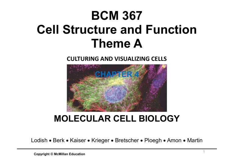
BCM 367 Cell Structure and Function Theme A CULTURING AND VISUALIZING CELLS CHAPTER 4 MOLECULAR CELL BIOLOGY Lodish Berk Kaiser Krieger Bretscher Ploegh Amon Martin Copyright © McMillan Education 1 CULTURING AND VISUALIZING CELLS What do we know about cells, And why do we know it? Lodish et al. Molecular Cell Biology 2 BCM367 THEME A: CULTURING, VISUALIZING AND PERTURBING CELLS Culturing and Visualizing Cells 4.1 Growing and Studying Cells in Culture 4.2 Light Microscopy: Exploring Cell Structure and Visualizing Proteins Within Cells 4.3 Electron Microscopy: High-Resolution Imaging 4.4 Isolation of Cell Organelles BCM367 THEME A: CULTURING, VISUALIZING AND PERTURBING CELLS History 1665 Robert Hooke – dead cells 1674 Antonie van Leeuwenhook – living cells 1838 Matthias Schleiden – All plants are made of cells 1839 Theodore Schwann – All animals are made of cells 1858 Rudolf Virchow – All cells came from pre-existing cells BCM367 THEME A: CULTURING, VISUALIZING AND PERTURBING CELLS - GROWING CELLS IN CULTURE 4 Culturing and Visualizing Cells 4.1 Growing and Studying Cells in Culture • Animal cells grow in culture when supplied with necessary nutrients and appropriate 2D or 3D substrates. • Primary cells have a finite life span; transformed tumor cells and cell line cells can grow indefinitely. • A fluorescence-activated cell sorter (FACS) sorts labeled cells. • Hybridoma cells produce monoclonal antibodies that bind one antigen epitope and are used for basic research and therapeutics. • Basic biological processes can be studied by using genetic manipulation or drugs to interfere with specific cell components. • Large chemical libraries can be screened for compounds that target specific processes. BCM367 THEME A: CULTURING, VISUALIZING AND PERTURBING CELLS - GROWING CELLS IN CULTURE Growing Cells in Culture Cell culture conditions Unicellular – fairly easy to grow (bacteria, fungi, protist) Multicellular organisms – more complex (ex. animal cells) Why do we grow cells and what do they need to grow? Animal Cells: Nutrient-Rich Media and Solid Surfaces o Mimic conditions in organisms tissues – pH, temperature, ionic strength, nutrients, etc. First needs: specially coated plastic dishes to adhere to and Liquid media (antibiotics added to prevent contamination) Liquid media: o 9 amino acids vertebrate animal cells are not capable to synthesise (phenylalanine, valine, threonine, tryptophan, isoleucine, methionine, leucine, lysine, histadine) o 3 amino acids only synthesised by specialised animal cells (cysteine, tyrosine, arginine) o Nitrogen source in the form of glutamine o Vitamins, salts, fatty acids, glucose o Serum – protein factors essential for proliferation of mammalian cells, insulin, transferrin (bio-accessible form of iron), growth factors o Growth factors specific for certain cell types BCM367 THEME A: CULTURING, VISUALIZING AND PERTURBING CELLS - GROWING CELLS IN CULTURE 6 Growing Cells in Culture Primary vs. transformed cell cultures Primary cell cultures formed from tissues like skin kidney liver etc. o Cell-cell and cell-matrix interaction must be disrupted to form these primary cultures – protease (eg. Trypsin,collagenase) and a divalent cation chelator (removes free Ca2+ eg. EDTA) treatments assist in this o Released cells moved to dishes with nutrient broth and serum for adherance to take place o Most cultured cells divide a set amount of time and then performs cell senescence and ceases to grow – the big (–)’ve Oncogenic mutations Figure 9.1 Stages in the establishment of a cell culture. o Embryonic stem cell – can be cultured indefinitely 7 BCM367 THEME A: CULTURING, VISUALIZING AND PERTURBING CELLS - GROWING CELLS IN CULTURE Growing Cells in Culture Primary vs. transformed cell cultures Research purposes require cells that double more than 50 times o Indefinite growth by oncogenically TRANSFORMED cells due to mutations – give rise to immortal cell lines Often spontaneous in rodents not so in humans For humans malignant tumor can be the source of such cell lines - HeLa cell line 1952 – cervical cancer Cultured HeLa cells with a fluorescent protein targeted to the Scanning electron micrograph of an Golgi (orange), microtubules (green) apoptotic HeLa cell and DNA (cyan) National Institutes of Health (NIH) National Institutes of Health (NIH) 8 BCM367 THEME A: CULTURING, VISUALIZING AND PERTURBING CELLS - GROWING CELLS IN CULTURE We have cells We know how to grow them What now? 9 Isolation – Flow Cytometry and Cell Sorting How do we separate cells? o Density – red blood cells vs. white blood cells – equilibrium density centrifugation o Often its not that easy – FLOW CYTOMETRY AND CELL SORTING o Cell surface molecules used to mark cells (fluorescent dye conjugated to antibody) BCM367 THEME A: CULTURING, VISUALIZING AND PERTURBING CELLS - GROWING CELLS IN CULTURE Isolation – Flow Cytometry and Cell Sorting How do we separate cells? o Density – red blood cells vs. white blood cells – equilibrium density centrifugation o Often its not that easy – FLOW CYTOMETRY AND CELL SORTING o Cell surface molecules used to mark cells (fluorescent dye conjugated to antibody) FLOW CYTOMETER: cells flow in liquid stream past a laser beam scattered light is measured and cells marked with specific fluorescence is identified Fluorescence-activated cell sorting (FACS) o Ink jet technology combined with the old Coulter cell counter o Cells identified through flow cytometry o Stream breaks into small drops each containing one cell o Charge laid onto drop and positive and negatively charged drops are separated by voltage plates Experimental Figure 9.3 T cells bound to fluorescence-tagged antibodies to two cell-surface proteins are separated from other white blood cells by FACS. 11 BCM367 THEME A: CULTURING, VISUALIZING AND PERTURBING CELLS - GROWING CELLS IN CULTURE Isolation – Flow Cytometry Figure 9.2 Fluorescence-activated cell sorter (FACS) separates cells that are labeled differentially with a fluorescent reagent. 12 BCM367 THEME A: CULTURING, VISUALIZING AND PERTURBING CELLS - GROWING CELLS IN CULTURE Isolation – Flow Cytometry 20 000 cells per second 13 BCM367 THEME A: CULTURING, VISUALIZING AND PERTURBING CELLS - GROWING CELLS IN CULTURE Two and Three Dimensional Growth Mimics In Vivo Environment Most tissue types function with cells in relation to each other and in close contact Good example: Epithelial sheets found in epithelial tissue – covering for external and internal surfaces of organs Epithelial cells transport classes of molecules across the epithelial sheet On plastic or glass – this function is limited Special containers with porous surfaces (acting as basal lamina) have been designed – gives rise to a two dimensional uniform sheet 2D vs 3D Figure 9.4 Madin-Darby canine kidney (MDCK) cells grown in specialized containers provide a useful experimental system for studying epithelial cells. 14 BCM367 THEME A: CULTURING, VISUALIZING AND PERTURBING CELLS - GROWING CELLS IN CULTURE I have isolated a new drug effective against a human cell pathogen. I want to test its effectiveness. How important is cell culturing to me? 15 Complexity meets the specific research question Natural media - Natural culture media is composed of biological fluids that are naturally occurring. Artificial media - Also referred to as synthetic media Selective media - Only allows for certain cells to grow. Differential media - Depending on metabolism. Serum containing media Serum-free media - avoid misinterpretation of immunological results. Chemically defined media - Contamination- free pure organic and inorganic ingredients. Protein-free media - Promote superior growth of the cells as well as protein expression in addition to facilitating for the purification of any expressed product. 16 Light Microscopy - Overview Magnification of a small object – light microscopy: 0.2 m resolution Bright Field Light Microscopy: o Total magnification = objective lens lens (ocular or eye piece) (closest to object) as well as the projection o Magnification vs. resolution: The ability to distinguish between two very closely positioned objects 17 BCM367 THEME A: CULTURING, VISUALIZING AND PERTURBING CELLS – LIGHT MICROSCOPY Light Microscopy - Overview 18 BCM367 THEME A: CULTURING, VISUALIZING AND PERTURBING CELLS – LIGHT MICROSCOPY Light Microscopy - Overview Magnification of a small object – light microscopy: 0.2 m resolution Bright Field Light Microscopy: o Total magnification = objective lens (closest to object) as well as the projection lens (ocular or eye piece) Range of angles over which the microscope can accept light Refractive index Angular aperture o Magnification vs. resolution: The ability to distinguish between two very closely positioned objects Resolution (D) = the minimum distance between two distinguishable objects the smaller the resolution - the better the image (Ernst Abbe late 19th century) D= 0.61 N sin (the numerical aperture; range from 1.4 for good to 1.7 for19 BCM367 THEME A: CULTURING, VISUALIZING AND PERTURBING CELLS – LIGHT MICROSCOPY excellent) Light Microscopy - Resolution = the angular aperture of the cone of the light entering the objective lens N = refractive index of the medium between the objective lens and specimen (air = 1 and oil or glass = 1.56 = wavelength of incident light How do I improve resolution? o Using shorter wavelengths of light o Gathering more light by increasing N or o Using oil which has a higher refractive index than air or water Lenses can focus very close to the cover slip Figure 9.8a Optical microscopes are commonly configured for bright-field (transmitted), phasecontrast, and epifluorescence microscopy. 20 BCM367 THEME A: CULTURING, VISUALIZING AND PERTURBING CELLS – LIGHT MICROSCOPY Light Microscopy - Resolution Mathematical exercise: What is the resolution (D) of light microscope X if it has an angular aperture of 60, refractive index of oil, and a wavelength of incident light of 700nm Resolution is in micrometers Wavelength is in micrometers D= 0.61 N sin D= 0.61 X 0.7 1.56 X sin 60 21 BCM367 THEME A: CULTURING, VISUALIZING AND PERTURBING CELLS – LIGHT MICROSCOPY Phase Contrast and Differential-Interference-Contrast Microscopy Visualising unstained living cells Bright field optics is the most simple method of viewing How light propagates through a medium Cellular materials have differences in their refractive indexes and thickness Utilized by Phase-contract microscopy and Differential-interference-contrast (DIC) microscopy Figure 9.9 Live cells can be visualized by microscopy techniques that generate contrast by interference. The degree of darkness or brightness of a region of the sample depends on the refractive index of that region –light moves slower in object with high refractive index DIC is based on interference between polarized light specially good for visualizing small details and thick objects – contrast generated by differences in the refractive index of the object and its surrounding medium 22 BCM367 THEME A: CULTURING, VISUALIZING AND PERTURBING CELLS – LIGHT MICROSCOPY Phase Contrast and Differential-Interference-Contrast Microscopy Light passing through specimen is refracted in comparison with light just moving through - this places it in a different phase In phase brighter than out of phase Allows specimen to be illuminated by defocused, parallel light wave fronts Figure 9.8b-d Optical microscopes are commonly configured for bright-field (transmitted), phasecontrast, and epifluorescence microscopy. 23 BCM367 THEME A: CULTURING, VISUALIZING AND PERTURBING CELLS – LIGHT MICROSCOPY Diatoms are singlecelled algae, live in houses made of glass. They are the only organism on the planet with cell walls composed of transparent, opaline silica. Phase contrast vs DIC 1min 6:13min 24 Fixing, Sectioning and Staining Cells Live cells lack compound to absorb light – how can we visualize more detail? Specimens are commonly fixed – treated with chemicals that link proteins and nucleic acids o Formaldehyde cross-links amino groups on adjacent molecules stabilize protein-protein and protein-nucleic acid interaction = molecules insoluble and stable o Can be left in solution or cut into sections Figure 9.10 Tissues for light microscopy are commonly fixed, embedded in a solid medium, and cut into thin sections. Staining o Various amount of stains for specific molecules in cells 25 BCM367 THEME A: CULTURING, VISUALIZING AND PERTURBING CELLS – LIGHT MICROSCOPY Fluorescence o Fluorescence occur when an electron is excited by light to a higher orbital and falls back to the ground state, giving off light in the process o Fluorochromes are dyes that accept light energy and re-emit light at longer wavelength and at different color than the absorbed light o Emitted light has longer wavelength AND less energy than absorbed light EXCITATION (LASER) 26 VS. EMISSION (DETECTOR) Fluorescence Microscopy Localizing and Quantifying Live Cell Molecules When are chemicals fluorescent? o It absorbs light at one wavelength (excitation) o It emits light at a specific longer wavelength (emission) o Laser = excitation o Detection = emission Fluorescent Microscopes: o Excitation light is passed through the objective into the sample, then selective viewing of emission through objective again o Reflected excitation light is deflected by dichroic mirror – allowing longer wavelength to pass through 27 BCM367 THEME A: CULTURING, VISUALIZING AND PERTURBING CELLS – LIGHT MICROSCOPY 495nm/519nm Excitation/Emission Laser/Detector 28 7 examples of fluorescent microscopy 1. Ion Sensitive Fluorescent Dyes 2. Immunofluorescence and specific proteins in fixed cells 3. Fluorescent proteins tag specific proteins in living cells 4. Light Microscopy – 3D confocal and deconvolution 5. TIRF Microscopy 6. FRAP 7. FRET 29 Example no. 1 Ion Sensitive Fluorescent Dyes There are Fluorochromes whose fluorescence depends on the concentration of Ca2+ and H+ What else do we know about Ca2+ and H+? – Many cellular processes are affected by their concentrations fura-2 – five carboxylate groups – can form ester linkages with ethanol = fura-2 ester o Fura-2 ester is lipophilic – diffuses across plasma membranes o In cytosol: - esterases hydrolyse fura-2 ester = non-liphophilic fura-2 unable to cross - one fura-2 binds one Ca2+ ion fura-2 +Ca2+ 340nm Excitation back over membrane 510nm Emission fura-2 +Ca2+ AND fura-2 380nm Excitation 510nm Emission BOUND AND UNBOUND fluorescence has TWO EXCITATION WAVELENGTHS – this can determine the ratio of Ca2+ and small changes that are occurring in the cell – increase of bound Ca2+ over time Experimental Figure 9.11 Fura-2, a Ca2+-sensitive fluorochrome, can be used to monitor the relative concentrations of cytosolic Ca2+ in different regions of live cells. 30 BCM367 THEME A: CULTURING, VISUALIZING AND PERTURBING CELLS – LIGHT MICROSCOPY Ion Sensitive Fluorescent Dyes SNARF-1 – sensitive to H+ is used to monitor intracellular pH levels Fluorochrome linked to a weak base – partially protonated at pH7 - can freely permeate membranes when entering acidic organelles – probes become protonated; cannot cross back over membranes and accumulates Used to stain lysosomes and mitochondria Experimental Figure 9.12 Location of lysosomes and mitochondria in a cultured living bovine pulmonary artery endothelial cell. WHAT TOOL ARE WE USING? 31 BCM367 THEME A: CULTURING, VISUALIZING AND PERTURBING CELLS – LIGHT MICROSCOPY 7 examples of fluorescent microscopy 1. Ion Sensitive Fluorescent Dyes 2. Immunofluorescence and specific proteins in fixed cells 32 Immunofluorescence and specific proteins in fixed cells Example no. 2 In response to infection, vertebrate immune systems produces antibodies Can identify and bind to specific infectious agents In vivo production of antibodies, and isolation via affinity chromatography -polyclonal – when animals blood is used -monoclonal – when one specific cell line is produced to collect antibody 1. FIXING THE CELLS: for protein localization, the cell needs to be ‘frozen’ or fixed to keep all components in place 2. PERMEABILIZING THE CELLS: allow entry of antibody (incubate cells in non-ionic detergent or extracting lipids through use of organic solvent) Figure 9.13 A specific protein can be localized in fixed tissue sections by indirect immunofluorescence microscopy. Indirect immunofluorescence microscopy 1. Cells treated with unlabelled antibody 2. Cells treated with second fluorescence tagged antibody that binds to first antibody Unbound antibodies washed away between steps Covalent attachment of fluorescent tag to antibody or protein - conjugation 33 BCM367 THEME A: CULTURING, VISUALIZING AND PERTURBING CELLS – LIGHT MICROSCOPY 7 examples of fluorescent microscopy 1. Ion Sensitive Fluorescent Dyes 2. Immunofluorescence and specific proteins in fixed cells 3. Fluorescent proteins tag specific proteins in living cells 34 Fluorescent proteins tag specific proteins in living cells Fluorescent expression through green fluorescent protein (GFP) Aequorea victoria GFP: contains serine, tyrosine, and glycine with spontaneously cyclizing side chains – forming a green fluorescing chromophore Example no. 3 Ssblakely Recombinant DNA techniques produces – GFP coupled proteins - Allows the localization of the fused, expressed protein in the cell Figure 9.15 Many different colors of fluorescent proteins are now available. Experimental Figure 9.14 Double-label fluorescence microscopy can visualize the relative distributions of two proteins. BCM367 THEME A: CULTURING, VISUALIZING AND PERTURBING CELLS – LIGHT MICROSCOPY 35 7 examples of fluorescent microscopy 1. Ion Sensitive Fluorescent Dyes 2. Immunofluorescence and specific proteins in fixed cells 3. Fluorescent proteins tag specific proteins in living cells 4. Light Microscopy – 3D confocal and deconvolution 36 Light Microscopy – 3D confocal and deconvolution Example no. 4 Experimental Figure 9.16 Deconvolution fluorescence Conventional fluorescent microscopy microscopy yields high-resolution optical sections that Limited by: can be reconstructed into one three-dimensional image. 1. Emitted fluorescent light comes from (a) (b) more than one plane – blurred image 2. Thick specimen observation requires consecutive images at various depths 2 Methods for High resolution 3D information - image data collected electronically for both to allow computational editing Deconvolution Microscopy Computational methods to remove out of focus planes Achieved by creating a test slide with a series of images of fluorescent beads o Create a point spread function, to calculate the distribution of fluorescent point sources that contributed to the ‘blur’ o The microscope calibration enables image series computational deconvolution Creates un-blurred images 37 BCM367 THEME A: CULTURING, VISUALIZING AND PERTURBING CELLS – LIGHT MICROSCOPY (a) (b) 38 39 3D confocal Confocal microscopy – optical methods to obtain images from specific planes. Excluding light from other planes Collect a series of images through the vertical depth of the sample TWO TYPES: point scanning and spinning disk HOW DOES IT WORK? Illuminate and collect emitted fluorescent light in just one small area of the focal plane at a time – this excludes the out-of-focus light A pinhole is used to collect the light before it reaches the detector The whole object is scanned and the image is built up electronically HOW DO THE TWO METHODS COVER THE IMAGE? Figure 9.17 Light paths for two types of confocal microscopy. 40 BCM367 THEME A: CULTURING, VISUALIZING AND PERTURBING CELLS – LIGHT MICROSCOPY 3D confocal Point scanning: o A point laser light is used, with the correct excitation wavelength, to scan the focal plane Excitation/ /Emission 41 BCM367 THEME A: CULTURING, VISUALIZING AND PERTURBING CELLS – LIGHT MICROSCOPY 3D confocal Point scanning: o A point laser light is used, with the correct excitation wavelength, to scan the focal plane 42 BCM367 THEME A: CULTURING, VISUALIZING AND PERTURBING CELLS – LIGHT MICROSCOPY 3D confocal Point scanning: o A point laser light is used, with the correct excitation wavelength, to scan the focal plane o Emitted fluorescence is collected by a photomultiplier tube o Image is built up electronically oTo create a 3D image - a series of images at different depths are collected + = High resolution - = 1. to scan each focal plane can be time consuming 2. intense laser light can bleach the fluorochrome Dynamic images might not be captured - Limited time to expose to laser BCM367 THEME A: CULTURING, VISUALIZING AND PERTURBING CELLS – LIGHT MICROSCOPY 43 3D confocal Spinning disk: Tries to solve point scanning problems – by using a spread out laser beam o Two fast spinning disks containing 20 000 microlenses and 20 000 pinholes respectively; precisely aligned 44 BCM367 THEME A: CULTURING, VISUALIZING AND PERTURBING CELLS – LIGHT MICROSCOPY 3D confocal Spinning disk: Tries to solve point scanning problems – by using a spread out laser beam o Two fast spinning disks containing 20 000 microlenses and 20 000 pinholes respectively; precisely aligned o With each spin the focal plane is scanned several times o Light returning passes through pinholes again into digital camera 45 BCM367 THEME A: CULTURING, VISUALIZING AND PERTURBING CELLS – LIGHT MICROSCOPY 3D confocal Spinning disk: Tries to solve point scanning problems – by using a spread out laser beam o Two fast spinning disks containing 20 000 microlenses and 20 000 pinholes respectively; precisely aligned o With each spin the focal plane is scanned several times o Light returning passes through pinholes again into digital camera + = Very fast - = usually only configured for 63X or 100X magnification (tissue samples need lower magnifications) BCM367 THEME A: CULTURING, VISUALIZING AND PERTURBING CELLS – LIGHT MICROSCOPY Excitation/ /Emission 46 3D confocal Figure 9.18 Confocal microscopy produces an in-focus optical section through thick cells. Experimental Figure 9.19 The dynamics of microtubules can be imaged on the spinning disk confocal microscope. 47 BCM367 THEME A: CULTURING, VISUALIZING AND PERTURBING CELLS – LIGHT MICROSCOPY 7 examples of fluorescent microscopy 1. Ion Sensitive Fluorescent Dyes 2. Immunofluorescence and specific proteins in fixed cells 3. Fluorescent proteins tag specific proteins in living cells 4. Light Microscopy – 3D confocal and deconvolution 5. TIRF Microscopy 48 TIRF Microscopy Example no. 5 Experimental Figure 9.20 Fluorescent samples in a restricted focal plane can be imaged by total internal reflection (TIRF) microscopy. Confocal microscopy not ideal to see interaction in thin focal plane close to cover slip (like adhesion) Total Internal Reflective Fluorescence (TIRF) Microscopy 49 BCM367 THEME A: CULTURING, VISUALIZING AND PERTURBING CELLS – LIGHT MICROSCOPY Example no. 5 TIRF Microscopy Experimental Figure 9.20 Fluorescent samples in a restricted focal plane can be imaged by total internal Confocal microscopy not ideal to see interaction in thin focal plane close to cover slip (like adhesion) Total Internal Reflective Fluorescence (TIRF) Microscopy reflection (TIRF) microscopy. oExcitation comes through the objective lens oAdjust the angle at which the cover slip is reached precisely at the correct angle to reflect it back up the objective BCM367 THEME A: CULTURING, VISUALIZING AND PERTURBING CELLS – LIGHT MICROSCOPY 50 TIRF Microscopy Example no. 5 Experimental Figure 9.20 Fluorescent samples in a restricted focal plane can be imaged by total internal Confocal microscopy not ideal to see interaction in thin focal plane close to cover slip (like adhesion) reflection (TIRF) microscopy. Total Internal Reflective Fluorescence (TIRF) Microscopy oExcitation comes through the objective lens oAdjust the angle at which the cover slip is reached precisely at the correct angle to reflect it back up the objective oEvanescent wave created - narrow band that only illuminate the 50 to 100 nm next to the cover slip Excellent observations on the structures of microtubules and actin filaments BCM367 THEME A: CULTURING, VISUALIZING AND PERTURBING CELLS – LIGHT MICROSCOPY 51 7 examples of fluorescent microscopy 1. Ion Sensitive Fluorescent Dyes 2. Immunofluorescence and specific proteins in fixed cells 3. Fluorescent proteins tag specific proteins in living cells 4. Light Microscopy – 3D confocal and deconvolution 5. TIRF Microscopy 6. FRAP 52 Example no. 6 FRAP How dynamic are certain cellular components Ex GFP – does the green fluorescence represent a stable group of proteins, or proteins that are dynamic and can move around? Fluorescent recovery after photo bleaching Experimental Figure 9.21 Fluorescence recovery o Use a high intensity light to bleach an already emitting fluorochrome in one specific area o if dynamic the dark, bleached area will have fluorescent component returning o can be observed with fluorescent microscope o rate of recovery measures the dynamics of molecules after photobleaching (FRAP) reveals the dynamics of molecules. Lateral movements of Specific plasma membrane proteins and lipids can be quantified by FRAP MDougM BCM367 THEME A: CULTURING, VISUALIZING AND PERTURBING CELLS – LIGHT MICROSCOPY 53 7 examples of fluorescent microscopy 1. Ion Sensitive Fluorescent Dyes 2. Immunofluorescence and specific proteins in fixed cells 3. Fluorescent proteins tag specific proteins in living cells 4. Light Microscopy – 3D confocal and deconvolution 5. TIRF Microscopy 6. FRAP 7. FRET 54 Example no. 7 FRET Do certain proteins interact in vivo? Förster resonance energy transfer – two fluorescent proteins where the emission wavelength of the first is equal to the excitation wavelength of the second German physical chemist Cyan fluorescent protein and yellow fluorescent protein as example Excitation/ /Emission critical Figure 9.22 Protein-protein interactions can be visualized by FRET. 55 BCM367 THEME A: CULTURING, VISUALIZING AND PERTURBING CELLS – LIGHT MICROSCOPY Example no. 7 FRET German physical chemist Do certain proteins interact in vivo? Förster resonance energy transfer – two fluorescent proteins where the emission wavelength of the first is equal to the excitation wavelength of the second Cyan fluorescent protein and yellow fluorescent protein as example YFP needs to be close by for fluorescent excitation to take place Energy transfer efficiency proportional to R6 R is the distance between the fluorophores Very sensitive and not detectable if R is >10 nm R Figure 9.22 Protein-protein interactions can be visualized by FRET. BCM367 THEME A: CULTURING, VISUALIZING AND PERTURBING CELLS – LIGHT MICROSCOPY 56 FRET-sensor application Chameleon sensor for measuring intracellular levels of Ca2+ One polypeptide with two sensors – CFP and YFP (joined by Ca2+ binding polypeptide) No Ca2+ no FRET – CFP and YFP to far apart Ca2+ binds – conformational change brings CFP and YFP close enough for FRET to occur 10nm > R Experimental Figure 9.23 FRET biosensors can detect local biochemical environments. 57 BCM367 THEME A: CULTURING, VISUALIZING AND PERTURBING CELLS – LIGHT MICROSCOPY
