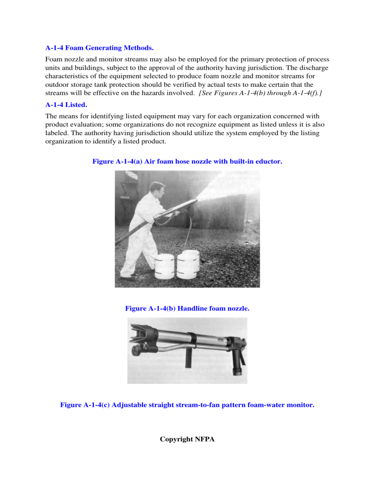
A-1-4 Foam Generating Methods. Foam nozzle and monitor streams may also be employed for the primary protection of process units and buildings, subject to the approval of the authority having jurisdiction. The discharge characteristics of the equipment selected to produce foam nozzle and monitor streams for outdoor storage tank protection should be verified by actual tests to make certain that the streams will be effective on the hazards involved. [See Figures A-1-4(b) through A-1-4(f).] A-1-4 Listed. The means for identifying listed equipment may vary for each organization concerned with product evaluation; some organizations do not recognize equipment as listed unless it is also labeled. The authority having jurisdiction should utilize the system employed by the listing organization to identify a listed product. Figure A-1-4(a) Air foam hose nozzle with built-in eductor. Figure A-1-4(b) Handline foam nozzle. Figure A-1-4(c) Adjustable straight stream-to-fan pattern foam-water monitor. Copyright NFPA Figure A-1-4(d) Adjustable straight stream-to-spray foam-water monitor. Figure A-1-4(e) Wheeled portable foam-water monitor. Figure A-1-4(f) Portable foam-water monitor. Copyright NFPA A-1-4 Proportioning Methods for Air Foam Systems. (c) In-Line Educator. This eductor is for installation in a hoseline, usually at some distance from the foam maker or playpipe, as a means of drafting air foam concentrate from a container. [See Figures A-1-4(g) and (h).] It has the following limitations: (a) The in-line eductor must be designed for the flow rate of the particular foam maker or playpipe with which it is to be used. The device is very sensitive to downstream pressures and accordingly is designed for use with specified lengths of hose or pipe located between it and the foam maker. (b) The pressure drop across the eductor is approximately one-third of the inlet pressure. (c) The elevation of the bottom of the concentrate container should not be more than 6 ft (1.8 m) below the eductor. (d) Metered Proportioning. By means of an auxiliary pump, foam compound is injected into the water stream passing through an inductor. The resulting foam solution is then delivered to a foam maker or playpipe. The proportioner can be inserted into the line at any point between the water source and foam maker or playpipe. [See Figures A-1-4(i) and (j).] Figure A-1-4(g) In-line eductor. Copyright NFPA To operate, the main water valve is opened and a reading of the pressure indicated on the duplex gauge is taken. When both gauge hands are set at the same point, the proper amount of foam concentrate is being injected into the water stream. This is done automatically by the use of a differential pressure diaphragm valve. Metered proportioning has the following limitations: (a) The capacity of the proportioner can be varied from approximately 50 percent to 200 percent of its rated capacity. (b) The pressure drop across the proportioner ranges from 5 psi to 30 psi (34 kPa to 207 kPa), depending on the volume of water flowing through the proportioner within the capacity limits of item (a) above. (c) A separate pump is needed to deliver concentrate to the proportioner. (e) Pressure Proportioning Tank. This method employs water pressure as the source of power. With this device, the water supply pressurizes the foam concentrate storage tank. At the same time, water flowing through an adjacent venturi or orifice creates a pressure differential. The low-pressure area of the venturi is connected to the foam concentrate tank, so that the difference between the water supply pressure and this low-pressure area forces the foam concentrate through a metering orifice and into the venturi. Also, the differential across the venturi varies in proportion to the flow, so one venturi will proportion properly over a wide flow range. The pressure drop through this unit is relatively low. [See Figure A-1-4(k).] A special test procedure is available to permit the use of a minimum amount of concentrate when testing the pressure proportioner system. The pressure proportioning tank has the following limitations: (a) Foam concentrates with specific gravities similar to water can create a problem when mixed. (b) The capacity of these proportioners can be varied from approximately 50 percent to 200 percent of their rated capacity. (c) The pressure drop across the proportioner ranges from 5 psi to 30 psi (34 kPa to 207 kPa), depending on the volume of water flowing within the capacity limits of item (b) above. (d) When the concentrate is exhausted, the system must be turned off, and the tank drained of water and refilled with foam concentrate. (e) Since water enters the tank as the foam concentrate is discharged, the concentrate Copyright NFPA supply cannot be replenished during operation, as with other methods. (f) This system proportions at a significantly reduced percentage at low flow rates and should not be used below minimum design flow rate. Diaphragm (Bladder) Pressure Proportioning Tank. This method also uses water pressure as a source of power. This device incorporates all the advantages of the pressure proportioning tank with the added advantage of a collapsible diaphragm that physically separates the foam concentrate from the water supply. Diaphragm pressure proportioning tanks operate through a similar range of water flows and according to the same principles as pressure proportioning tanks. The added design feature is a reinforced elastomeric diaphragm (bladder) that can be used with all concentrates listed for use with that particular diaphragm (bladder) material. [See Figure A-1-4(l).] Figure A-1-4(h) In-line eductor. Figure A-1-4(i) Balanced pressure proportioning with single injection point (metered proportioning). Copyright NFPA The proportioner is a modified venturi device with a foam concentrate feed line from the diaphragm tank connected to the low-pressure area of the venturi. Water under pressure passes through the controller, and part of this flow is diverted into the water feed line to the diaphragm tank. This water pressurizes the tank, forcing the diaphragm filled with foam concentrate to slowly collapse. This forces the foam concentrate out through the foam concentrate feed line and into the low-pressure area of the proportioner controller. The concentrate is metered by use of an orifice or metering valve and mixes in the proper proportion with the main water supply, sending the correct foam solution downstream to the foam makers. Figure A-1-4(j) Balanced pressure proportioning with multiple injection points (metered proportioning). Copyright NFPA Figure A-1-4(k) Typical arrangement of pressure proportioning tank. The limitations are the same as those listed above for the pressure proportioning tank except the system can be used for all types of concentrates. Copyright NFPA


