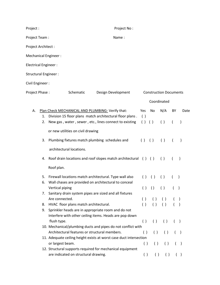
Project : Project No : Project Team : Name : Project Architect : Mechanical Engineer : Electrical Engineer : Structural Engineer : Civil Engineer : Project Phase : Schematic Design Development Construction Documents Coordinated A. Plan Check MECHANICAL AND PLUMBING- Verify that: Yes No 1. Division 15 floor plans match architectural floor plans . ( ) 2. New gas , water , sewer , etc., lines connect to existing ( ) ( ) N/A BY Date ( ) ( ) ( ) ( ) ( ) 4. Roof drain locations and roof slopes match architectural ( ) ( ) ( ) ( ) ( ) ( ) ( ) ( ) ( ) ( ) ( ( ) ) ( ) ( ) ( ) ( ) ( ) ( ) ( ) ( ) or new utilities on civil drawing 3. Plumbing fixtures match plumbing schedules and ( ) architectural locations. Roof plan. 5. Firewall locations match architectural. Type wall also ( ) ( ) 6. Wall chases are provided on architectural to conceal Vertical piping ( ) () 7. Sanitary drain system pipes are sized and all fixtures Are connected. ( ) ( ) 8. HVAC floor plans match architectural. ( ) ( ) 9. Sprinkler heads are in appropriate room and do not Interfere with other ceiling items. Heads are pop down flush type. ( ) ( ) 10. Mechanical/plumbing ducts and pipes do not conflict with Architectural features or structural members. ( ) ( ) 11. Adequate ceiling height exists at worst case duct intersection or largest beam. ( ) ( ) 12. Structural supports required for mechanical equipment are indicated on structural drawing. ( ) ( ) 13. Dampers are indicate at smoke and fire walls. ( ) ( ) ( ) 14. Diffuser locations match architectural reflected ceiling plans.( ) ( ) ( ) 15. Openings for roof penetrations (ducts, fans, etc.) are indicated On structural roof plans. ( ) ( ) ( ) 16. Notes are referenced. ( ) ( ) ( ) 17. Air conditioning units, heaters, and exhaust fans match Architectural roof plan. ( ) ( ) ( ) 18. Mechanical equipment will fit in spaces allocated and that ( ) ( ) ( ) There is room For maintenance such as removing filters or tubes. 19. Horsepower ratings, phases, and voltages of major items of Equipment on mechanical and electrical drawings and specifications match ( ) ( ) ( ) 20. Thermostat locations have been coordinated with ( ) ( ) ( ) architectural drawings 21. Verify and coordinate building roof drain line connecting to Storm system. ( ) ( ) ( ) Coordinated Yes No N/A 22. Verify all underslab roof drain and other storm line ( if ( ) ( ) ( ) Location outsie of building limits is impractical) are cast Iron by Division 15. 23. Confirm nature and extend of potential conflicts in elevations ( ) ( ) ( ) Between underground site utilities including underground Electrical duct banks. 24. Locate all underground utilities a minimum of 36’’ below grade ( ) ( ) ( ) At mobile technology sites. 25. Confirm two source water feed on hospital sites to meet code ( ) ( ) ( ) requirement for dual fire protection feed. 26. Verify that static and residual water pressures on the site ( ) ( ) ( ) ( building and street hydrants ) have been verified. 27. Check for interference with underground utilities and ( ) ( ) ( ) grade beams. 28. Crawl space depth to be sufficient for personnel movement ( ) ( ) ( ) Below cast iron and other utility work. 29. Ascertain impact of all new underground utilities on pavement, ( ) ( ) ( ) Curbs, traffic flow, etc. coordinate with architectural phasing plans. 30. Confirm all post indicator valves have supervisory switch tie-ins. ( ) ( ) ( ) 31. Determine extent,nature and requirements for new utility ( ) ( ) ( ) Penetrations through existing foundation walls. Structural Engineer input 32. Site fire hydrant locations to be approved by local fire marshal. ( ) ( ) ( ) 33. If boilers are oil fed, confirm that oil tank and day tank ( ) ( ) ( ) Configuration allows for low temperature supply. ( ( ) ) ( ( ) ) ( ( ) ) ( ( ) ) ( ) By Date ( ) ( ) ( ) ( ) ( ) ( ) ( ) ( ) ( ( ) ) ( ( ) ) 34. Confirm status and responsibility for existing underground ( ) ( ) ( ) ( ) fule oil storage tank removal. New tanks to be above ground. 35. Check for interference between drain lines/footing etc. ( ) ( ) ( ) ( ) 36. Cross check architectural crawlspace extent against that ( ) ( ) ( ) ( ) Shown on mechanical plans. 37. Confirm site survey shows depth of all Division ( ) ( ) ( ) ( ) 15 underground utilities. 38. Confirm locations of the following exterior building items Against architectural plans: A. Overflow Drains ( ) ( ) ( ) ( ) B. Fire Hydrants and Standpipe station ( ) ( ) ( ) ( ) C. Hose Spigots ( ) ( ) ( ) ( ) D. Irrigation System Components. ( ) ( ) ( ) ( ) 39. Double check architectural storm drainage structure numbers ( ) ( ) ( ) ( ) And locations against architectural and civil storm drainage plans. 40. Confirm new underground utilities do not conflict with light poles ( ) ( ) ( ) ( ) 41. Check for adequate clearance between new and existing ( ) ( ) ( ) ( ) underground utilities and new grade elevation. Check loading docks. Pit depths. 42. Confirm city tie-in requirements for new utilities out to street ( ) ( ) ( ) ( ) Show actual tie-ins and who is responsible. 43. Code water meter pit locations against new sidewalk. ( ) ( ) ( ) ( ) 44. Verify standpipe hose cabinets (with extinguisher) have been ( ) ( ) ( ) ( ) provided per code. Check against architectural. If fed frome bottom, not to be over beam. Confirm wall depth. 45. Confirm State reqirements for sprinkler protection in the following areas: A. Operating Rooms ( ) ( ) ( ) ( ) B. Electrical Gear Rooms ( ) ( ) ( ) ( ) C. Computer Rooms ( ) ( ) ( ) ( ) D. Elevator shafts ( ) ( ) ( ) ( ) Verify if Halon systems are allowed by the State and E.P.A. In the following: 1. Computer Rooms ( ) ( ) ( ) ( ) 2. M.R.I. and other sensitive equipment Rooms ( ) ( ) ( ) ( ) E. X-ray film file rooms are to be water sprinklered ( ) ( ) ( ) ( ) 46. Confirm fire pump size, amperage and emergency power ( ) ( ) ( ) ( ) Tie-in. Confirm with electrical. 47.Confirm if building is high-rise. Confirm all requirements with respect to: 48. 49. 50. 51. 52. 53. 54. 55. 56. 57. 58. 59. 60. 61. 62. 63. Yes ( ) ( ) ( ) ( ) ( ) Coordinated No N/A By ( ) ( ) ( ) ( ) ( ) ( ) ( ) ( ) ( ) ( ) ( ) ( ) ( ) ( ) ( ) A. Standpipes B. Smoke Proof Towers C. Smoke Evacuation D. Etc. Confirm code requirements for smoke evacuation versus Removal requirements in the mechanical system. Confirm System designed per code. For vertical duct chases, confirm floor or wall dampers. ( ) ( ) ( ) Check against architectural and structural for floor Penetrations. Rated Shafts . Check for interference between angle iron bracing and The following: A. Perimeter ducts as exterior walls, storefronts ( ) ( ) ( ) B. Interior ducts at interior storefronts, movable Wall, etc., framing. ( ) ( ) ( ) Confirm ductwork is not centered on and running parallel ( ) ( ) ( ) With rated walls. All ductwork penetrations through rated walls to ( ) ( ) ( ) be perpendicular. Confirm all ceiling access door requirements and locations ( ) ( ) ( ) against architectural ceiling plans. In renovated construction, provide new chase space for ( ) ( ) ( ) vertical pipe runs As required. Confirm all vertical chase and wall furring requirements ( ) ( ) ( ) for vertical pipe runs. Overlay architectural plans on plumbing plans. Confirm ( ) ( ) ( ) Locations of all roof drains and vertical pipe runs. Confirm Metal stud depth. Confirm recessed Architectural accessory Location conflicts. Confirm floor drain and curb locations in mechanical rooms. ( ) ( ) ( ) Confirm Owner preferred medical gas outlets are specified. ( ) ( ) ( ) Confirm medical gas zone valve box locations against ( ) ( ) ( ) architectural plans. Confirm adequate space and wall depth for installation. Confirm roof top mechanical equipment controller locations. ( ) ( ) ( ) Confirm sump drains provided at elevator pits and other pits ( ) ( ) ( ) as required. Confirm mechanical room louver requirements. Size, location,( ) ( ) ( ) blank off panels and airflow resistance. Provide acoustical separation for interior mechanical rooms. ( ) ( ) ( ) ( ) ( ) ( ( ) ) ( ) ( ) ( ) ( ) ( ) ( ) ( ) ( ) ( ( ) ) ( ) ( ) Date 64. Confirm Owner requested deep , double sink locations. ( ) ( ) ( ) ( ) Provide adequate cabinet depth. 65. Confirm film processor rough-in and vent requirements. ( ) ( ) ( ) ( ) 66. Confirm adequate air flow for high B.T.U. areas such as labs ( ) ( ) ( ) ( ) film illuminator banks, computer rooms, telecommunication llosets, etc. Computer rooms to be maintained at 60 degree F Confirm requirements with Owner. Check electrical drawing for location. 67. Confirm all Biological Hood venting, utility airflow ( ) ( ) ( ) ( ) requirements . Provide drains as needed. 68. In Laboratories, confirm histology tabletop venting ( ) ( ) ( ) ( ) requirements 69. Confirm all clean-out locations. Locate so as not to occure ( ) ( ) ( ) ( ) In public spaces. In carpeted areas, provide with carpet plug. 70. Confirm all handicapped toilet, lavatory locations. ( ) ( ) ( ) ( ) 71. Confirm Owner requested bed pan flushing requirements ( ) ( ) ( ) ( ) on toilets 72. Confirm routing of all utilities to exterior wall fan coil units. ( ) ( ) ( ) ( ) 73. Confirm how linear diffusers are to interface with ( ) ( ) ( ) ( ) ceiling grids. To one side of spline, split the tile, or take the place of the spline. Include nite on details. 74. No ductwork over radiology rooms. ( ) ( ) ( ) ( ) 75. Confirm all medical gas placements coincide with ( ) ( ) ( ) ( ) Architectural elevations and owner requirements. 76. Check all fixed hospital equipment locations. ( ) ( ) ( ) ( ) 77. Confirm scrub sinks have adequate wall space ( ) ( ) ( ) ( ) for 6” each side. 78. Confirm glass shading coefficients and room top insulation ( ) ( ) ( ) ( ) Values with Architectural plans. 79. For laboratory and pharmacy casework, double check ( ) ( ) ( ) ( ) Connection and installation requirements, i.e.: who Furnishes traps, tailpieces, etc.; and who installs. 80. Confirm methods employed for vibration isolation of ( ) ( ) ( ) ( ) mechanical equipment. Do not locate mechanical units at midspan in long direction. Confirm concerns with Structural Engineer. 81. For firestopping purposes, confirm mechanical and ( ) ( ) ( ) ( ) Demolition drawings provided enough information for Adequste firestopping bid. 82. At pediatric rooms, confirm negative pressure rooms. ( ) ( ) ( ) ( ) 83. Identify all negative pressure isolation rooms. ( ) ( ) ( ) ( ) 84. Check de-watering requirements for deep underground ( ) ( ) ( ) ( ) Utilities against subsurface report. 85. Confirm patient room handicapped fiberglass shower locations ( ) ( ) ( ) ( ) Against ceramic tile showers. 86. In renovation, confirm existing ceilings that are removed, ( ) ( ) ( ) ( ) Reinstalled for installation of new services. Confirm who patches. Coordinated Yes No N/A BY Date 87. All public toilets wall mounted unless owner approves otherwise. ( ) ( ) ( ) ( ) 88. Floor mounted toilets at all two-hour wall unless Architect ( ) ( ) ( ) ( ) approves . 89. On demolition plans, confirm fixtures removed, remaining. ( ) ( ) ( ) ( ) Check against architectural demolition plans. 90. Confirm building steam, steam traps at sterilizers. ( ) ( ) ( ) ( ) 91. Overlay structural framing plan on plumbing plans to confirm ( ) ( ) ( ) ( ) drain lines do not occur over beams. 92. In demolition, confirm extent of existing wall and hard ceiling ( ) ( ) ( ) ( ) patchwork fir new utility installation and tie in. Follow utilities down through floor slab. 93. On roofs designed for vertical expansion, ensure all vent stacks ( ) ( ) ( ) ( ) are located outside of column cap extension enclosures. 94. Confirm Division 15 provided sterilizer exhaust hood need and ( ) ( ) ( ) ( ) requirements. Check ceiling heights. 95. In demolition, confirm new fire dampers in existing walls that ( ) ( ) ( ) ( ) are upgraded. 96. Confirm U.L. labeled ceiling, floor or roof assembly locations. ( ) ( ) ( ) ( ) Confirm U.L. Alternare A or B duct penetration protection provided. 97. Check ductwork configuration at operating rooms for ( ) ( ) ( ) ( ) Interference with light, gas column supports. 98. Confirm water cooler locations. Check against architectural. ( ) ( ) ( ) ( ) 99. Clearance for coil pull out in mechanical rooms provided. ( ) ( ) ( ) ( ) 100. Interlock wiring on lab fume and biological cabinets. ( ) ( ) ( ) ( ) 101. Confirm thermostat cover types with Owner. ( ) ( ) ( ) ( ) 102. Oxygen and vacuum outlets are spaced properly. Slides ( ) ( ) ( ) ( ) placement works with Owner vacuum equipment. 103. Mechanical rooms are ventilated. ( ) ( ) ( ) ( ) 104. Corrosion resistant ductwork at chemical storage exhaust. ( ) ( ) ( ) ( ) 105. Indoor air quality meets ASHRAE Standard 62-89. ( ) ( ) ( ) ( ) 106. Medical gas certification from Owner prior to renovation. ( ) ( ) ( ) ( ) 107. Mechanical loads for renovation based on existing envelope. ( ) ( ) ( ) ( ) 108. Does building meet energy design code requirements. ( ) ( ) ( ) ( ) 109. Adjustable shivs on A.H.U. fan pulleys to facilitate static ( ) ( ) ( ) ( ) pressure adjustments at Test & Balance. Also final filters replaced during test and balance. Coordinated Yes No N/A BY Date ( ) ( ) ( ) ( ) 110. Kitchen hoods specified and furnished under Division 15 for balance reason . 111. Architect /Owner has reviewed cut sheets on all plumbing ( ) ( ) ( ) ( ) fixtures. 112. Sterilizers to be piped in to allow for required clearances. ( ) ( ) ( ) ( ) 113. Vacuum slides specified without backboxes. ( ) ( ) ( ) ( ) 114. Condition of existing risers verified prior to renovation. ( ) ( ) ( ) ( ) Secure direction from Owner for replacement. 115. Investigate means of existing support for pipe, conduit, etc. ( ) ( ) ( ) ( ) Cover in contract documents. 116. Engineer needs to review Architect front end specification. ( ) ( ) ( ) ( ) Coordinate for submittals, substantial completion of System, warranties , etc. 117. Vibration Isolation. Acoustical tests for all mechanical room ( ) ( ) ( ) ( ) and other isolated equipment. 118. Carpet markers at all floor cleanouts in carpet. ( ) ( ) ( ) ( ) 119. Precast terrazzo clinical bases specified under Division 15. ( ) ( ) ( ) ( ) 120. Mop basins have tile flanges. Mop basins specified fit in rooms. ( ) ( ) ( ) ( ) 121. Offset traps specified at all lavatory counters with sloping skirts.( ) ( ) ( ) ( ) 122. Drain line can get down in outside column enclosures. ( ) ( ) ( ) ( ) 123. Rough-in countertop ice machines from below. ( ) ( ) ( ) ( ) 124. Ceiling lights are to be shown on mechanical plans. ( ) ( ) ( ) ( ) 125. Roof drain leaders are extended out to storm lines in field. ( ) ( ) ( ) ( ) Not just stop at 5’ outside building. 126. All cast-iron storm sewer work is picked up under Division 15. ( ) ( ) ( ) ( ) 127. Vacuum breaker assemblies for clinical sinks do not interfere ( ) ( ) ( ) ( ) With wall cabinetry above. 128. All ductwork and piping over 2” in diameter passes thru rated ( ) ( ) ( ) ( ) Wall at 90-degree agle. 129. Piping sleeve details thru rated walls approved by code ( ) ( ) ( ) ( ) Authorities. 130. Pneumatic control systems and materials approved by Owner’s ( ) ( ) ( ) ( ) Maintenance staff. 131. Trial operational and seasonal change over periods of time are ( ) ( ) ( ) ( ) Established for all new mechanical systems prior to Substantial Completion acceptance. 132. Medical gas riser valves identified to meet code requirements. ( ) ( ) ( ) ( ) Establish multiple certifications for phased construction. 133. Do not tie new pneumatic control systems into existing ( ) ( ) ( ) ( ) equipment Coordinated Yes No N/A BY Date 134. Interlock wiring provided for all biological/hot lab hoods. ( ) ( ) ( ) 135. Chemical storage areas are exhausted directly into the outside. ( ) ( ) ( ) 136. X-ray rom medical gases are located behind the table. ( ) ( ) ( ) 137. Provide at least two vacuum outlets and one scavenger vacuum ( ) ( ) ( ) Outlet for each procedure or operating room. 138. Disconnects provided at all roof top fans and other monitors. ( ) ( ) ( ) 139. All fire protection valves are supervised. Chains not permitted. ( ) ( ) ( ) 140. Minimum two season balance of HVAC systems specified. ( ) ( ) ( ) 141. Elevator shafts sprinklered per code. ( ) ( ) ( ) 142. A.H.U. shut down switches at Nurses Station. Confirm smoke ( ) ( ) ( ) evacuation considerations. 143. Fire alarm matrix is prepared by mechanical Engineer and ( ) ( ) ( ) Coordinated with Electrical Engineer. Covered in Specs. 144. Elevator shafts above code levels are vented ( ) ( ) ( ) 145. Vacuum slides specified without backboxes. ( ) ( ) ( ) 146. Eyewash stations per OSHA are provided in all labs and Film ( ) ( ) ( ) Processing rooms. ( ( ( ( ) ) ) ) ( ( ( ( ( ) ) ) ) ) ( ) ( ) ( ) ( )


