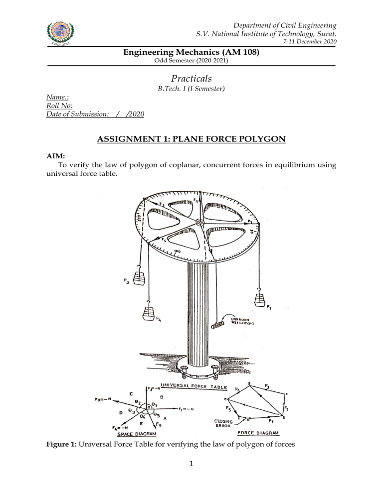
Department of Civil Engineering S.V. National Institute of Technology, Surat. 7-11 December 2020 Engineering Mechanics (AM 108) Odd Semester (2020-2021) Practicals B.Tech. I (I Semester) Name.: Roll No: Date of Submission: / /2020 ASSIGNMENT 1: PLANE FORCE POLYGON AIM: To verify the law of polygon of coplanar, concurrent forces in equilibrium using universal force table. Figure 1: Universal Force Table for verifying the law of polygon of forces 1 THEORY: (1) Law of polygon of forces: “More than three coplanar forces acting at a point which are in equilibrium can be represented in magnitude and direction by sides of a closed polygon taken in order”; (2) Concurrent forces: Forces whose line of action passes through a point are called concurrent forces; (3) Coplanar forces: Forces acting in one plane are called coplanar forces; (4) Equilibrium: When the resultant of forces acting on a particle is zero, the particle will not be displaced and hence the particle can be called to be in equilibrium under the action of this system of forces; Let a system of five coplanar forces acting at a point O is in equilibrium as shown in Figure 1. Let the force polygon of this system of forces has closing error fa. The resultant of forces F2 and F3 may be represented by side ___ ___ ___ bd . Similarly, resultant of bd and F4 is represented by be . If the system of ___ forces is in equilibrium, then the force triangle formed by forces be , F5 and F1 must be close (Law of triangle). As a result, the polygon of given system of forces must also be close. There should not be a closing error, end points a and f of force polygon must be coincide; and (4) Resolution of forces: Under equilibrium condition, resultant of given force system, R = 0. Burt, R = RX2 + RY2 , where, RX and RY are rectangular components of R. Hence, RX = 0 and RY = 0; But, RX = ΣFX = 0, and RY = ΣFY = 0. Σ FX = F1X + F2X+ F3X+ F4X +F5X = Sum of x components of all forces. Σ FY = F1Y + F2Y+ F3Y+ F4Y +F5Y = Sum of y components of all forces. Signature of student: _____________ 2 PROCEDURE: (1) Level the force table with the help of spirit level by adjusting foot screws; (2) Adjust the weights and subtended angles such that the center of ring coincides with central pivot; (3) Note down the magnitude of forces and the subtended angles between them; (4) Repeat the experiment with different weights and subtended angles; (5) Draw space diagram for these sets of observations to a suitable scale; (6) Use Bow’s notation to identify forces; (7) Draw polygon of forces by drawing its sides parallel to corresponding forces in order to represent them both in magnitude and direction; (8) Join the tail of first forces vector to tip of last force vector by dotted closing line; (9) Measure the length of closing line which gives the magnitude of error; (10) (a) Determine the unknown weight of block, P; and (b) Determine the unknown weight of block, P and Q. EXERCISES: (1) Using Universal force table, verify the equilibrium condition; (2) Determine the unknown weight of block, P and Q jointly; and (3) Verify the equilibrium condition by the method of resolution of forces. Signature of student: _____________ 3 OBSERVATION TABLE: Magnitude of Forces (N) (Include weight of hooks) S.No. Subtended angles (Degree) (Between forces) F1 F2 F3 F4 F5 F1-F2 F2-F3 F3-F4 F4-F5 F5-F1 1 X.0 X.5 X.7 X+1 X.0 50º 80º 100º 60º 70º 2 X.5 X.5 X.0 X.6 X.1 83º 61º 75º 71º 70º 3 X.5 X.0 X.1 X.7 X.0 60º 90º 50º 100º 60º 4 X.5 X+1.2 X.5 X+1 X.0 30º 130º 40º 70º 90º 5 X.0 X.0 X.0 X.0 X.0 72º 72º 72º 72º 72º F1 F2 F3 F4 P F1-F2 F2-F3 F3-F4 F4-F5 F5-F1 6 X.0 X.3 X.0 X.0 P 65º 85º 60º 70º 80º 7 X.1 X.2 X.0 X.6 P 80º 40º 100º 70º 70º F1 F2 F3 P Q F1-F2 F2-F3 F3-F4 F4-F5 F5-F1 8 X.5 X.5 X.5 P Q 90º 65º 45º 100º 60º 9 X.0 X.7 X.7 P Q 90º 80º 50º 100º 40º Note: P and Q are unknown weights; X is the last digit of Student’s Roll No., e.g., U20CE001, X.0 = 01.0, X.5 = 1.5, X + 1.2 = 2.2. Roll number ending with Zero may consider the second last digit, U20CE010, X.0 = 1.0, X.5 = 1.5, X + 1.2 = 2.2. Signature of student: _____________ 4 GRAPHICAL METHOD (SAMPLE DIAGRAM) Signature of student: _____________ 5 GRAPHICAL METHOD Signature of student: _____________ 6 ANALYTICAL METHOD (Calculations) Signature of student: _____________ 7 RESULTS AND CONCLUSIONS: P= N (by force polygon) P= N (by method of resolution of forces) P= N (Actual) Signature of student: _____________ 8 Q= Q= forces) Q= N (by force polygon) N (by method of resolution of N (Actual)
