International Journal of Trend in Scientific Research and Development (IJTSRD)
Volume 4 Issue 6, September-October 2020 Available Online: www.ijtsrd.com e-ISSN: 2456 – 6470
Comparative Study of Concrete T Beam Girder Bridge under
IRC Loading Conditions using STADD Pro V8i Software
Abhinav Kumar1, Nitesh Kushwaha2
1M
Tech Scholar, 2Professor,
1,2Department of Civil Engineering, Millennium Institute of Technology & Science,
Bhopal, Madhya Pradesh, India
ABSTRACT
In this study, a comparative study based on different type of bridges i.e. Deck
using finite element analysis in STAAD PRO is prepared, considering same
loading class 70-R as per I.R.C. loading, comparative study based on different
types of bridges that is simple girder deck and T Beam girder, two models
have been prepared for the consideration of the study.
How to cite this paper: Abhinav Kumar |
Nitesh Kushwaha "Comparative Study of
Concrete T Beam Girder Bridge under IRC
Loading Conditions using STADD Pro V8i
Software" Published
in
International
Journal of Trend in
Scientific Research
and Development
(ijtsrd), ISSN: 24566470, Volume-4 |
IJTSRD33306
Issue-6,
October
2020,
pp.96-103,
URL:
www.ijtsrd.com/papers/ijtsrd33306.pdf
STAAD PRO software which is based on the application of Finite Element
Method. This software is a widely used in the field of structural design and
analysis. Now a day this software is very much friendly for the analysis of
different type of structures and to calculate the result at every node & element
wise.
Copyright © 2020 by author(s) and
International Journal of Trend in Scientific
Research and Development Journal. This
is an Open Access article distributed
under the terms of
the
Creative
Commons Attribution
License
(CC
BY
4.0)
(http://creativecommons.org/licenses/by
/4.0)
INTRODUCTION
T-BEAM
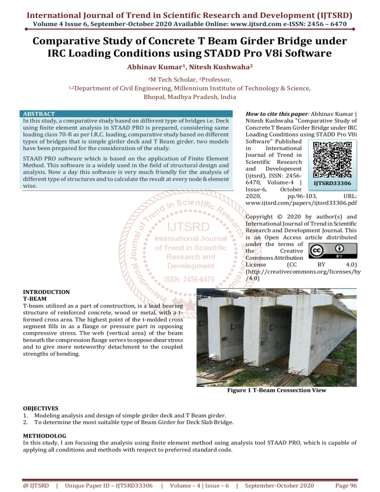
T-beam utilized as a part of construction, is a load bearing
structure of reinforced concrete, wood or metal, with a tformed cross area. The highest point of the t-molded cross
segment fills in as a flange or pressure part in opposing
compressive stress. The web (vertical area) of the beam
beneath the compression flange serves to oppose shear stress
and to give more noteworthy detachment to the coupled
strengths of bending.
Figure 1 T-Beam Crossection View
OBJECTIVES
1. Modeling analysis and design of simple girder deck and T Beam girder.
2. To determine the most suitable type of Beam Girder for Deck Slab Bridge.
METHODOLOG
In this study, I am focusing the analysis using finite element method using analysis tool STAAD PRO, which is capable of
applying all conditions and methods with respect to preferred standard code.
@ IJTSRD
|
Unique Paper ID – IJTSRD33306
|
Volume – 4 | Issue – 6
|
September-October 2020
Page 96
International Journal of Trend in Scientific Research and Development (IJTSRD) @ www.ijtsrd.com eISSN: 2456-6470
Figure 2 T Beam Bridge
Figure 3 Ordinary deck 3D view
RESULTS
Comparison Between Ordinary Beam Deck & T Beam Ordinary Deck.
Max Displacement
T Beam Ordinary Deck shows least displacement in all conditions i.e. 4.145mm, 34.378 mm, 25.271 mm in X, Y & Z
directions in comparison to Ordinary Beam Deck 7.116mm, 38.742 mm, 29.672 mm in X, Y & Z directions.
Table 1 Shows Comparison of Displacement for Ordinary Beam and T Beam
Ordinary Beam Deck T Beam Ordinary Deck
X mm
X mm
Max X 7.116
4.145
@ IJTSRD
|
Max Y
Ordinary Beam Deck
Y mm
38.742
T Beam Ordinary Deck
Y mm
34.378
Max Z
Ordinary Beam Deck
Z mm
29.672
T Beam Ordinary Deck
Z mm
25.271
Unique Paper ID – IJTSRD33306
|
Volume – 4 | Issue – 6
|
September-October 2020
Page 97
International Journal of Trend in Scientific Research and Development (IJTSRD) @ www.ijtsrd.com eISSN: 2456-6470
Max Displacement Graphs
Graphs Shows Comparison of Displacement for Ordinary Beam and T Beam Deck
Fig.4: Max. Displacement in X Direction
Fig.5: Max. Displacement in Y Direction
@ IJTSRD
|
Unique Paper ID – IJTSRD33306
|
Volume – 4 | Issue – 6
|
September-October 2020
Page 98
International Journal of Trend in Scientific Research and Development (IJTSRD) @ www.ijtsrd.com eISSN: 2456-6470
Fig.6: Max. Displacement in Z Direction
Max Forces and Moment
T Beam Ordinary Deck shows least shear force in all conditions i.e., 9744.066 Kn, 2612.869 Kn & 411.447 Kn in X, Y & Z
directions in comparison to Ordinary Beam Deck.
T Beam Ordinary Deck shows least bending moment in all conditions i.e. 3260.751 Kn-m, 2602.017 Kn-m, 8558.537 Kn-m
in X, Y & Z directions in comparison to Ordinary Beam Deck.
Table 2 Shows Comparison of Max Forces and Moment for Ordinary Beam and T Beam Deck
Ordinary Beam Deck T Beam Deck
Fx kN
Fx kN
Max Fx
8447.702
9744.066
@ IJTSRD
|
Max Fy
Ordinary Beam Deck
Fy kN
3298.134
T Beam Deck
Fy kN
2612.869
Max Fz
Ordinary Beam Deck
Fz kN
2491.052
T Beam Deck
Fz kN
411.447
Unique Paper ID – IJTSRD33306
|
Volume – 4 | Issue – 6
|
September-October 2020
Page 99
International Journal of Trend in Scientific Research and Development (IJTSRD) @ www.ijtsrd.com eISSN: 2456-6470
Ordinary Beam Deck
Mx kNm
T Beam Deck
Mx kNm
Max Mx
1207.316
3260.751
Max My
Ordinary Beam Deck
My kNm
4202.252
T Beam Deck
My kNm
2602.017
Max Mz
Ordinary Beam Deck
Mz kNm
14848.575
T Beam Deck
Mz kNm
8558.537
Graphs Shows Comparison of Forces and Moment for Ordinary Beam and T Beam Deck
Fig.7: Max. Force in X Direction
@ IJTSRD
|
Unique Paper ID – IJTSRD33306
|
Volume – 4 | Issue – 6
|
September-October 2020
Page 100
International Journal of Trend in Scientific Research and Development (IJTSRD) @ www.ijtsrd.com eISSN: 2456-6470
Fig.8: Max. Force in Y Direction
Fig.9: Max. Force in Z Direction
@ IJTSRD
|
Unique Paper ID – IJTSRD33306
|
Volume – 4 | Issue – 6
|
September-October 2020
Page 101
International Journal of Trend in Scientific Research and Development (IJTSRD) @ www.ijtsrd.com eISSN: 2456-6470
Fig.10: Max. Bending Moment in X Direction
Fig.11: Max. Bending Moment in Y Direction
@ IJTSRD
|
Unique Paper ID – IJTSRD33306
|
Volume – 4 | Issue – 6
|
September-October 2020
Page 102
International Journal of Trend in Scientific Research and Development (IJTSRD) @ www.ijtsrd.com eISSN: 2456-6470
Fig. 5.9: Max. Bending Moment in Z Direction
CONCLUSION
T Beam Ordinary Deck shows least displacement in all
conditions i.e. 4.145mm, 34.378 mm, 25.271 mm in X, Y
& Z directions in comparison to Ordinary Beam Deck
7.116mm, 38.742 mm, 29.672 mm in X, Y & Z directions.
T Beam Ordinary Deck shows least shear force in all
conditions i.e., 9744.066 Kn, 2612.869 Kn & 411.447 Kn
in X, Y & Z directions in comparison to Ordinary Beam
Deck.
T Beam Ordinary Deck shows least bending moment in
all conditions i.e. 3260.751 Kn-m, 2602.017 Kn-m,
8558.537 Kn-m in X, Y & Z directions in comparison to
Ordinary Beam Deck.
REFERENCES
[1] N. K Paul, S. Shah, “Improvement of Load Carrying
Capacity of a RCC T-Beam Bridge Longitudinal Girder
by Replacing Steel Bars with S.M.A Bars”, World
Academy of Science, Engineering and Technology 2011.
[2] Praful NK, Balaso Hanumant, “Comparative Analysis of
T-BEAM Bridge by Rational Method and STADD PRO”,
International Journal of Engineering Science &
Research Technology, June 2015.
[3] R. Shreedhar, “Analysis of T-Beam bridge using FEM”,
International Journal of Engineering and Innovative
Technology (IJEIT), September 2012, Volume 2, Issue 3.
@ IJTSRD
|
Unique Paper ID – IJTSRD33306
|
[4] Rajmoori, Arun Kumar, “Design of Prestress Concrete
T-Beam”, International Journal of Scientific
Engineering and Research, 8 August 2014, Volume 2.
[5] Sandesh Upadhayay K, “A Comparative Study of TBeam Bridge for Varying Span Lenghts”, International
Journal of Research in Engineering Technology, June
2016, Issue 6, Vol. 5.
[6] Sandesh Upadhyaya K and F Sahaya Sachin, A
Comparative Study of T- Beam Bridges for varying span
lenths, International Journal of Research in
Engineering Technology, Vol 5, Jun 2016.
[7] Shetty RS, Prashanth MH, Channappa TM, Ravi Kumar
CM. Data vibration concealment of steel support
railroad connect utilizing tuned mass dampers. ISSN
1955:1298, Vol. 7, 2017.
[8] Soumya S and Umadevi R, Comparative Study of
Courbons Method and Finite Element Method of RC TBeam and Deck Slab Bridge, International Journal of
Engineering and Management Research, (IJEMR) Vol 5
Issue 6, Dec 2015.
[9] Y Yadu Priya and T Sujatha, Comparative Analysis of
Post Tensioned T-Beam Bridge Deck by Rational
Method and Finite Element Method, International
Journal of Research in IT, Management and
Engineering, Vol 6, Issuue 7, Sept 2016.
Volume – 4 | Issue – 6
|
September-October 2020
Page 103


