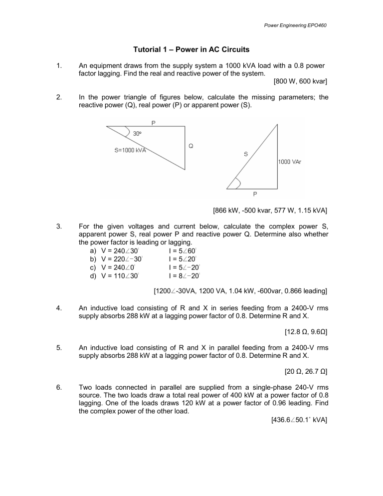
Power Engineering EPO460 Tutorial 1 – Power in AC Circuits 1. An equipment draws from the supply system a 1000 kVA load with a 0.8 power factor lagging. Find the real and reactive power of the system. [800 W, 600 kvar] 2. In the power triangle of figures below, calculate the missing parameters; the reactive power (Q), real power (P) or apparent power (S). [866 kW, -500 kvar, 577 W, 1.15 kVA] 3. For the given voltages and current below, calculate the complex power S, apparent power S, real power P and reactive power Q. Determine also whether the power factor is leading or lagging. a) V = 240∠30° I = 5∠60° I = 5∠20° b) V = 220∠−30° I = 5∠−20° c) V = 240∠0° I = 8∠−20° d) V = 110∠30° [1200∠-30VA, 1200 VA, 1.04 kW, -600var, 0.866 leading] 4. An inductive load consisting of R and X in series feeding from a 2400-V rms supply absorbs 288 kW at a lagging power factor of 0.8. Determine R and X. [12.8 Ω, 9.6Ω] 5. An inductive load consisting of R and X in parallel feeding from a 2400-V rms supply absorbs 288 kW at a lagging power factor of 0.8. Determine R and X. [20 Ω, 26.7 Ω] 6. Two loads connected in parallel are supplied from a single-phase 240-V rms source. The two loads draw a total real power of 400 kW at a power factor of 0.8 lagging. One of the loads draws 120 kW at a power factor of 0.96 leading. Find the complex power of the other load. [436.6∠50.1˚ kVA] Power Engineering EPO460 7. The load shown below consists of a resistance R in parallel with a capacitor of reactance X. The load is fed from a single-phase supply through a line of impedance 8.4 + j11.2 Ω. The rms voltage at the load terminal is 1200∠0° V rms, and the load is taking 30 kVA at 0.8 power factor leading. a) Find the value of R and X b) Determine the supply voltage V [60 Ω, 80 Ω, 1250∠16.26˚ V] 8. Two impedances, Z1 = 0.8 + j5.6 Ω and Z2 = 8 − j16 Ω, and a single-phase motor are connected in parallel across a 200- V rms, 60Hz supply as shown in figure below. The motor draws 5 kVA at 0.8 power factor lagging. a) Find the complex power S1, S2 for the two impedances, and S3 for the motor. b) Determine the total power taken from the supply, the supply current, and the overall power factor. Power Engineering EPO460 9. Two single-phase ideal voltage sources are connected by a line of impedance of 0.7 + j2.4 Ω as shown below. V1 = 500∠16.26ᴼ V and V2 = 585∠0ᴼ V. Find the complex power for each machine and determine whether they are delivering or receiving real and reactive power. Also, find the real and the reactive power loss in the line.
