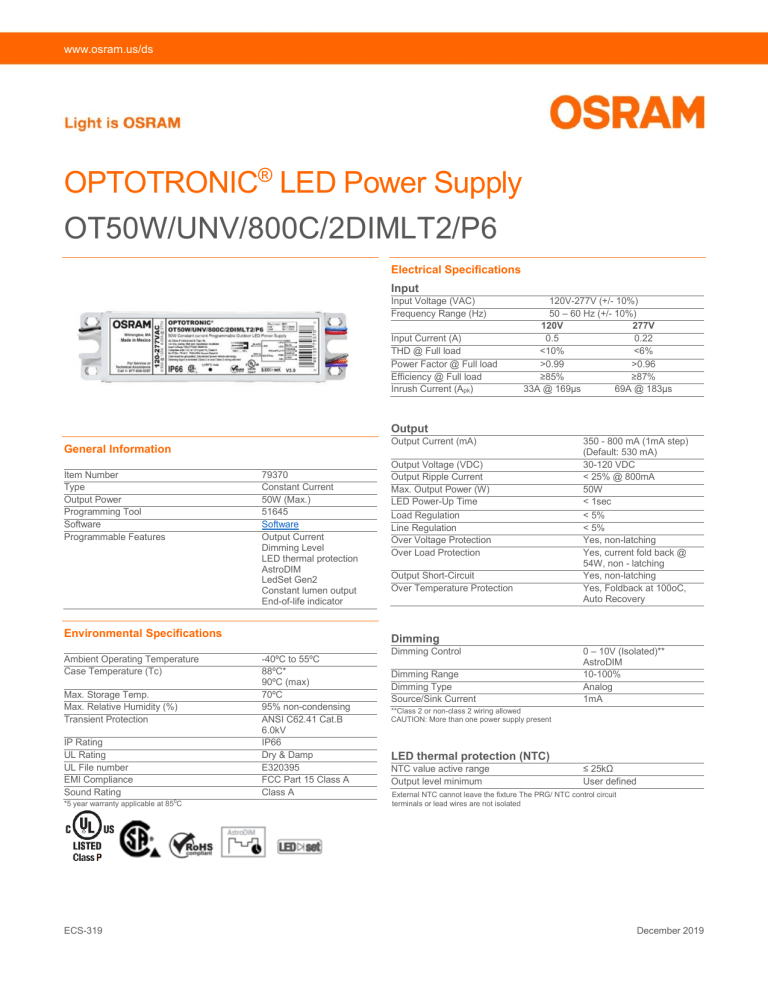
www.osram.us/ds OPTOTRONIC® LED Power Supply OT50W/UNV/800C/2DIMLT2/P6 Electrical Specifications Input Input Voltage (VAC) Frequency Range (Hz) Input Current (A) THD @ Full load Power Factor @ Full load Efficiency @ Full load Inrush Current (Apk) 120V-277V (+/- 10%) 50 – 60 Hz (+/- 10%) 120V 277V 0.5 0.22 <10% <6% >0.99 >0.96 ≥85% ≥87% 33A @ 169µs 69A @ 183µs Output Output Current (mA) General Information Item Number Type Output Power Programming Tool Software Programmable Features 79370 Constant Current 50W (Max.) 51645 Software Output Current Dimming Level LED thermal protection AstroDIM LedSet Gen2 Constant lumen output End-of-life indicator Environmental Specifications Ambient Operating Temperature Case Temperature (Tc) Max. Storage Temp. Max. Relative Humidity (%) Transient Protection IP Rating UL Rating UL File number EMI Compliance Sound Rating *5 year warranty applicable at 850C ECS-319 Output Voltage (VDC) Output Ripple Current Max. Output Power (W) LED Power-Up Time Load Regulation Line Regulation Over Voltage Protection Over Load Protection Output Short-Circuit Over Temperature Protection 350 - 800 mA (1mA step) (Default: 530 mA) 30-120 VDC < 25% @ 800mA 50W < 1sec < 5% < 5% Yes, non-latching Yes, current fold back @ 54W, non - latching Yes, non-latching Yes, Foldback at 100oC, Auto Recovery Dimming -40ºC to 55ºC 88ºC* 90ºC (max) 70ºC 95% non-condensing ANSI C62.41 Cat.B 6.0kV IP66 Dry & Damp E320395 FCC Part 15 Class A Class A Dimming Control Dimming Range Dimming Type Source/Sink Current 0 – 10V (Isolated)** AstroDIM 10-100% Analog 1mA **Class 2 or non-class 2 wiring allowed CAUTION: More than one power supply present LED thermal protection (NTC) NTC value active range Output level minimum ≤ 25kΩ User defined External NTC cannot leave the fixture The PRG/ NTC control circuit terminals or lead wires are not isolated December 2019 OT50W/UNV/800C/2DIMLT2/P6 Wiring Diagram Note: Maximum suggested remote mounting distance is 32 feet. For additional information on further distances and EMI compliance reference application note LED126. Mechanical Diagram Mechanical Specifications Length Width Height Mounting Length Mounting slot Width ECS-319 6.61” (168mm) 1.71” (43.5mm) 1.18” (30.0mm) 5.98” (152mm) 0.34” (8.7mm) OT50W/UNV/800C/2DIMLT2/P6 Operating Curve 130 Output Voltage (V) 110 90 70 50 30 10 300 400 500 600 700 800 900 Output Current (mA) Note: Power factor >0.9 and THD <20% at 120V and 277V Dimming Curve 100 % of Output current 80 60 40 20 0 0 1 2 3 4 5 Dim Voltage (V) ECS-319 6 7 8 9 10 OT50W/UNV/800C/2DIMLT2/P6 Efficiency vs. Output Voltage Efficiency @ 120V 88 86 84 Efficiency (%) 82 80 800mA 78 550mA 450mA 76 350mA 74 72 70 30 40 50 60 70 80 90 100 110 120 Output Voltage (V) Efficiency @ 277V 90 88 86 Efficiency (%) 84 800mA 82 550mA 80 450mA 78 350mA 76 74 72 70 30 40 50 60 70 80 Output Voltage (V) ECS-319 90 100 110 120 OT50W/UNV/800C/2DIMLT2/P6 Power Factor Performance 1.00 Power factor 0.96 0.92 120V 277V 0.88 0.84 0.80 10 20 30 40 50 Output Power (W) 1.00 Power factor 0.98 0.96 0.94 0.92 0.90 100 150 200 250 Input Voltage (VAC) ECS-319 300 350 OT50W/UNV/800C/2DIMLT2/P6 THD Performance 15 THD (%) 12 9 120V 6 277V 3 0 10 20 30 40 50 Output Power (W) 12 10 THD (%) 8 6 4 2 0 100 150 200 250 Input Voltage (VAC) ECS-319 300 350 OT50W/UNV/800C/2DIMLT2/P6 LED Thermal Protection (NTC) Characteristic The LED thermal protection feature of the OT50W helps reduce the temperature of the LED module by reducing the output current in case of abnormal temperature conditions. To use this feature a third party NTC thermistor should be connected to the LED power supply as shown in the wiring diagram below. In the end application, care must be taken to place the NTC thermistor close to the hottest spot on the LED module. If LED thermal protection is not required the NTC port on the LED power supply connector can be left open. Vishay, EPCOS, Murata, Panasonic are some of the manufacturers of NTC thermistor. EPCOS part number for reference only B57164K153J (15kΩ @ 25°C). Murata part number for reference only - NCP03XH223J05RL (22kΩ @ 25°C) For detailed information on LED Thermal Protection, please refer to Technical Application guide (ECS 304) Note: Graphs for reference. The de-rating limits can be programmed using the OT Programmer Derating start = 6.3kΩ; Derating end = 4.3kΩ; Min output level = 10% % Of Output Current 100 80 60 40 20 0 6.5 6 5.5 5 RNTC in kΩ 4.5 4 End of Life Indicator The End-of-Life indicator feature helps the end user to receive a signal from the fixture indicating that it has reached its programmed life-time. After the LED driver reaches the programmed life-time, whenever it is turned ON, it stays at ‘Dim’ level (10%) for 10 minutes and reaches its appropriate level. ECS-319 OT50W/UNV/800C/2DIMLT2/P6 AstroDIM AstroDIM is an autonomous five level (1 Power ON & 4 Dimming levels) dimming protocol. It provides multi-stage night-time power reduction based on an internal timer; there is no need for an external control infrastructure. The ECG is automatically aligned to the on and off times for the street lighting and provide a defined output for the particular period of time. Compared with conventional systems there are significant cost savings. AstroDIM is designed for dimming without any external control wiring. Therefore, AstroDIM helps to save energy, extend the life of the driver and the LED module and reduce light pollution, even if only a power line is available. In AstroDIM operation, the driver executes a preset dimming profile, which can be reconfigured via the OT Programming Tool. The autonomous dimming is regulated by an integrated timer (no real-time clock), which adjusts the dimming profile according to the previous night (operation from switch-on to switch-off). For detailed information on AstroDIM please refer to Technical Application guide 2DIM feature (LED 408) LEDset 2 LEDset (Gen2) is an analog interface, allowing basic communication between a LED control gear and one or more LED modules. It allows setting the output current of the LED driver by providing a highly accurate voltage reference (Vset) to the driver. The interface supports the following functions: Output current setting of the constant current LED control gear to single LED modules as well as to series/parallel connected LED modules Best matching of LED control gear and modules working point Self-configuration according to system structure, automatic tracking of technology development Easy mode of operation Additional monitoring & protection features (e.g. thermal protection of the LED modules) Therefore, the typical applications of this interface are single or multiple LED module parallel connections, offering an increasing choice of modular capabilities and low cost thermal protections circuits. For detailed information on LEDset interface please refer to Technical Application guide LEDset interface (LED 409) Note: When the LEDset feature is enabled, the LED Thermal protection (NTC) feature is disabled. Constant Lumen Maintenance The Constant Lumen Maintenance feature of the OTi200W helps to maintain the required lumen output of the fixture at a constant level throughout its lifetime. In general LED’s lumen output will depreciate over time and in order to maintain sufficient light level towards the end of lifetime, the LED’s are driven at high current initially and will result in more energy consumption. The constant lumen maintenance will give the flexibility to drive the LEDs at optimal driving current throughout its lifetime. This helps in energy savings, constant light output and enhanced reliability of the system. Note: A detailed step-by-step instructions are outlined in the ‘OT Programmer User Manual V2.1 ECS-319 OT50W/UNV/800C/2DIMLT2/P6 Lifetime vs TCase 120 100 Life time (kHrs) 80 60 40 20 0 30 40 50 60 70 80 90 Case Temperature (°C) Dimmer Compatibility Manufacturer Encelium LMS Leviton Lutron Wattstopper Synergy Lighting Controls Part Number EN-LCM-1R10V-GB2-BK EN-LCM-1R10V-GB2-BK/DR EN-ALC-1R10V-GB2-BK EN-ALC-1R10V-GB2-BK-DR IP710-DLZ DVTV-XX ADF-120277 ISD BC Note: The absence of a dimmer from this chart does not necessarily imply incompatibility. Please reference the dimmer manufacturer’s instructions for installation. Warranty OPTOTRONIC® products are covered by our LED Module, OPTOTRONIC Power Supply or Control Warranty. For additional details, refer to the latest version of the warranty (LED089) available at www.osram.us/optotronic OSRAM SYLVANIA Inc. 200 Ballardvale Street Wilmington, MA 01887 USA 877-636-5267 www.osram.us/ds ECS319 12-19 ECS-319
