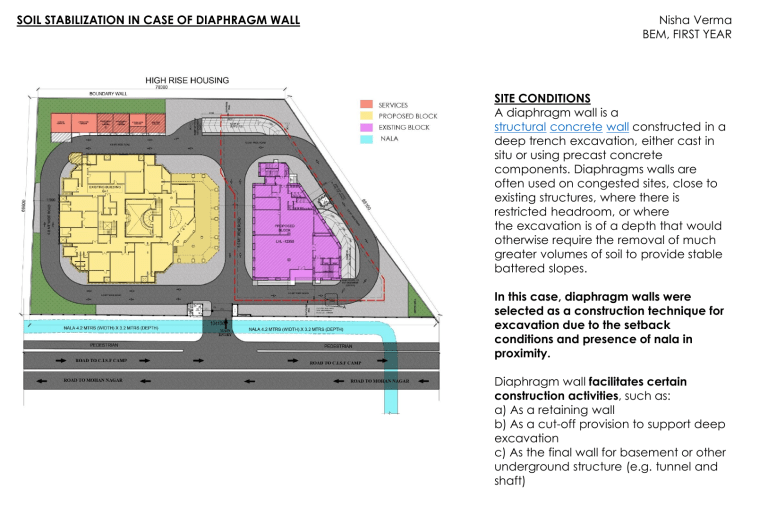
SOIL STABILIZATION IN CASE OF DIAPHRAGM WALL Nisha Verma BEM, FIRST YEAR SITE CONDITIONS A diaphragm wall is a structural concrete wall constructed in a deep trench excavation, either cast in situ or using precast concrete components. Diaphragms walls are often used on congested sites, close to existing structures, where there is restricted headroom, or where the excavation is of a depth that would otherwise require the removal of much greater volumes of soil to provide stable battered slopes. In this case, diaphragm walls were selected as a construction technique for excavation due to the setback conditions and presence of nala in proximity. Diaphragm wall facilitates certain construction activities, such as: a) As a retaining wall b) As a cut-off provision to support deep excavation c) As the final wall for basement or other underground structure (e.g. tunnel and shaft) Explanation on the work sequences Guide wall – Guide walls are constructed in-situ typically as lighly reinforced concrete elements. Guide walls maintain the horizontal allignment and wall continuity of a diaphragm wall while the provide support for the upper soils depth during panel excavation. This temporary support is important as the slurry levels vary during construction and the upper few feet or one meter of the wall tends to be unstable. Equally important, guide walls help guide the diaphragm wall grabs vertically and aid in the positioning of the final structure. Pre-excavation for diaphragm wall installation Prior to the diaphragm wall grabs starting excavation, the slurry pump must be fully submerged in bentonite slurry. To achieve this, a small initial excavation by the grab is carried out that is filled with slurry. Occasionally, some pre-excavation might be required before guide walls are installed to remove certain obstructions. Trench excavation –Excavation is done using a clamshell or grab suspended by cables to a crane. The grab can easily cut through soft ground. In case of encountering boulders, a gravity hammer (chisel) will be used to break the rock and then take the spoil out using the grab. Excavation support – the sides inside the trench cut can collapse easily. Bentonite slurry is used to protect the sides of soil. Bentonite is a specially selected fine clay, when added to water, forms an impervious cakelike slurry with very large viscosity. The slurry will produce a great lateral pressure sufficient enough to retain the vertical soil. it exerts a pressure in excess of the earth and hydrostatic pressures on the sides of the excavation. Slurry cleaning and desanding for diaphragm wall construction Prior to tremieying the concrete, and while the panel is excavated, the supporting slurry fluid must be cleaned so that it's properties are within acceptable levels (density, sand content, viscocity, PH). Slurry is circulated at regular intervals throughout the construction period through the regeneration plant. Otherwise, fresh slurry fluid can also be used although this approach is not the most economical. Joint constuction methods for diaphragm wall construction Diaphragm wall joints need to receive special attention do detail. Various joint types are available for diaphragm walls. Joint selection depends on the excavating equipment as much as contractor preference Joints can be flat, circular, with steel beams, or special grooved type with water stops. Grooved type joints with water stops are typically preferred while in the US it is also very common to use steel I beams for water stops. Flat panels and circular joints are generally avoided. Reinforcement cage lowering and concrete tremieing Once the bottom of the panel is reached (and cleaned), the reinforcement cage can be lowered into position. The reinforcement cage is typically suspended from the guide wall panels, and must have enough transverse and diagonal reinforcement to permit it to be properly lifted and lowered into place. Sufficient space must be left for at least two or three tremie pipes so that tremieing can take place. Concrete tremieing refers to the process of replacing the supporting slurry with the permanent concrete with the use of vertical pipes called tremies. With the tremies, concreting of a diaphragm wall starts from the bottom and the tremies are lifted progressively as the concrete level rises. During this process the tremies are maintained within the freshly poured concrete for a minimum depth of 2ft or (0.6m). Overpouring might be required to make sure that all slurry is displaced from the panel by concrete. Poor tremieing can result in slurry pockets getting entraped within the diaphragm wall concrete. These pockets can then lead to excessive and costly groundwater leaks or even blowouts. FORMING THE GUIDE WALL AND USING IT IN THE TRENCHING OPERATION Clamshell use to excavate the trench to form a diaphragm wall panel Bentenite slurry to balance the soil pressure to protect the trench from collapse Guide wall Trench excavation working in bentonite slurry with grab alignment control by guide wall Tongue and groove type stopend to form the joining for two adjacent diaphragm wall panel Fixing and placing of reinforcing cage de-sanding equipment Debris (sand and gravel) being filtered from the bontonite slurry and deposite to the storage tank Debris storage tank De-sanding equipment – the bontonite slurry carrying the soil and gravel re-circulate to this equipment with the bontonite slurry and the debris being removed. The debris will be collected in the storage tank for disposal later Diaphragm wall Diaphragm wall as cut-off for basement excavation Diaphragm wall TECHNICAL DRAWINGS PLAN GROOVE JOINT IN REINFORCEMENT SECTION 1 INSTRUCTIONS SPECIFIC TO SITE 1) Sodium bentonite powder shall be mixed thoroughly with potable water to form a fully dispersed lump-free homogeneous slurry. Suitable slurry tanks shall be used for this operation. The temperature of water used and of the slurry used shall not be less than 5°C. 2) The trench panel shall be kept filled with bentonite slurry of suitable consistency and viscosity during the excavation period. 3) Guide walls after construction should be suitably propped to maintain specified tolerance 4) Mesh or cage reinforcement hall be used in guide walls. 5) The level of bentonite slurry in the trench shall be 1 m or more, if necessary, higher than the ground water table. 6) Guide walls get support from adjoining panels and, therefore, their construction should be done continuously. 7) All work shall be carried out with guidelines from IS 9556 and IS-14344
